I tried to drive the flash device W25Q32 on ncs v1.3, but there was no proper spi routine to refer to.
I tried to drive the flash device W25Q32 on ncs v1.3, but there was no proper spi routine to refer to.
Hi,
It looks like there's an example for W25Qxx in zephyr, which you can try:
https://github.com/nrfconnect/sdk-zephyr/blob/master/samples/drivers/spi_flash/src/main.c
However; it does not have a board file for nrf9160, and I personally haven't tested the above sample.
Kind regards,
Håkon
HI HåkonAlseth,
I tried to open this project, but report an error.
The relevant screenshots are as follows:
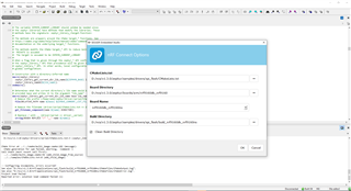
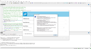
Kind regards, Peter.Min
Hi Peter,
I am not able to fully test this driver, but I created a configuration + dts overlay for W25Q32:
the .conf file goes into the ../spi_flash/boards/ folder, and the .overlay goes in ../spi_flash folder.
It tried atleast to read the JEDEC ID when I scoped the MOSI + CLK line:
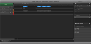
Could you try this configuration + overlay and see if it works/compiles at your end? Feel free to change the settings in the overlay file to match your GPIO settings and spi frequency etc.
Kind regards,
Håkon
Hi Håkon Alseth,
I test the example used ncs v1.3 on PCA10090 0.9.0
The example path is D:\ncs\v1.3.0\zephyr\samples\drivers\spi_flash\src\main.c
The overlay path is D:\ncs\v1.3.0\zephyr\samples\drivers\spi_flash\nrf9160dk_nrf9160ns.overlay
The conf path is D:\ncs\v1.3.0\zephyr\samples\drivers\spi_flash\boards\nrf9160dk_nrf9160ns.conf
The dts path is D:\ncs\v1.3.0\zephyr\boards\arm\nrf9160dk_nrf9160\nrf9160dk_nrf9160_common.dts
The log is as below:
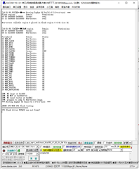
The cs-gpios = <&gpio0 13 0>; timing diagram is seems error.
The timing diagram is as below:
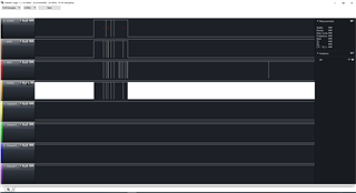
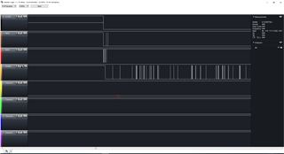
The test example is attached.
nrf9160测试demo.rar
Kind regards, Peter.Min
Hi,
Are you sure you have connected the grounding properly to the logic analyzer?
This is the scope I get when trying your code:
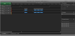
Kind regards,
Håkon
Hi,Håkon Alseth
This has little to do with the logic analyzer, just look at the log log and know that the w25q32 chip is not recognized.
Did you test with the development board PIN 10 11 12 13?
Kind regards, Peter.Min
Hi,Håkon Alseth
This has little to do with the logic analyzer, just look at the log log and know that the w25q32 chip is not recognized.
Did you test with the development board PIN 10 11 12 13?
Kind regards, Peter.Min
Hi Peter,
peter.min said:Did you test with the development board PIN 10 11 12 13?
Yes I did.
peter.min said:This has little to do with the logic analyzer, just look at the log log and know that the w25q32 chip is not recognized.
Yes, I understand that the log states that it cannot find the IC, but your logic analyzer trace is not correct; which is the first indication for us to see what happens on the actual SPI lines. Does the IC respond to the initial transaction, does it fail further in the init() structure?
Kind regards,
Håkon
I tested the routine you provided, which can be used,
But I made the following changes and couldn't use them.
The modifications are shown in the figure below:
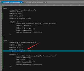
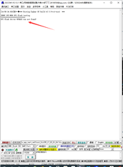
By making cs, these pins can detect the flash chip of the spi interface.
P0.00 01 13 14 15 26 27 08 09
When these pins are cs, the flash chip of the spi interface cannot be detected.
P0.19 18 17 02 03 04 05 06 07 20 21 22 23 24 25 19 18 17 30 31
Kind regards, Peter.Min
Hi Peter,
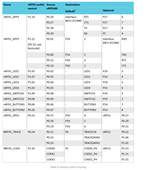
Some GPIOs are used for other purposes. Please see this list for the GPIOs that are already in use:
https://infocenter.nordicsemi.com/topic/ug_nrf91_dk/UG/nrf91_DK/board_controller.html?cp=2_0_5_4_6_0
Kind regards,
Håkon
Hi Håkon Alseth,
I'm using an empty board test,
No hardware affects the use of the corresponding IO port.
I also didn't find where P0.13 was occupied by the software.
P0.13 Why not be used as a CS foot.

Kind regards, Peter.Min
Hi Peter,
Can you please test this on another board, to rule out any issues with this specific board?
you can also modify the samples/basic/blinky/ to only toggle P0.13, to see if this blinks or not.
Kind regards,
Håkon