This post is older than 2 years and might not be relevant anymore
More Info: Consider searching for newer posts

ble_app_uart example some uart issue on fanstel EV-840 DK

Hi there,

I am using WIN10, Segger studio 4.52c and nRF SDK16. 

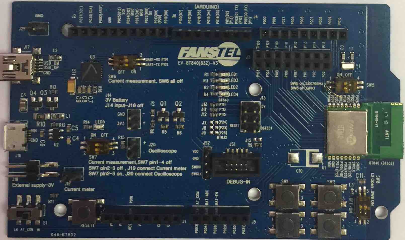
I can successfully run ble_app_uart example on PCA10056, but when i try to run same code on fanstel EV-840 dev board, application crashes after uart_init() function, actually APP_UART_COMMUNICATION_ERROR event is received in event handler. (if i comment uart_init() function everything else works fine.. i can connect with phone and all...)

Then i tried Uart example in  examples\peripheral\uart and i got the same behavior as in ble_app_uart.

But when i tried serial_uartes example in examples\peripheral\serial_uartes strangely enough this worked perfectly and i can send data on both the uarts.

So there is no hardware issue in UART for sure and i am using RX on 26 and TX on 27 on EV_840.

Now i am out of options to try out, please suggest what can be wrong and why i can't run ble_app_uart example on fanstel EV-840. 

I am sure i am missing something very basic.

Thanks, Rishi

  • Hi Rishi

    Does the EV-840 board have a 32.768kHz crystal included? I'm asking because the EV-840 modules do not but from this picture, it seems that the Y1 is an external crystal with an on/off switch. Please check whether this switch is in the ON position on your board, as all our SDK examples use the external 32.768kHz crystal by default. If you'd like to run the example without this crystal you can make the following changes to your sdk_config.h header file:

    // </h> 
    //==========================================================
    
    // <h> Clock - SoftDevice clock configuration
    
    //==========================================================
    // <o> NRF_SDH_CLOCK_LF_SRC  - SoftDevice clock source.
     
    // <0=> NRF_CLOCK_LF_SRC_RC 
    // <1=> NRF_CLOCK_LF_SRC_XTAL 
    // <2=> NRF_CLOCK_LF_SRC_SYNTH 
    
    #ifndef NRF_SDH_CLOCK_LF_SRC
    #define NRF_SDH_CLOCK_LF_SRC 0
    #endif
    
    // <o> NRF_SDH_CLOCK_LF_RC_CTIV - SoftDevice calibration timer interval. 
    #ifndef NRF_SDH_CLOCK_LF_RC_CTIV
    #define NRF_SDH_CLOCK_LF_RC_CTIV 16
    #endif
    
    // <o> NRF_SDH_CLOCK_LF_RC_TEMP_CTIV - SoftDevice calibration timer interval under constant temperature. 
    // <i> How often (in number of calibration intervals) the RC oscillator shall be calibrated
    // <i>  if the temperature has not changed.
    
    #ifndef NRF_SDH_CLOCK_LF_RC_TEMP_CTIV
    #define NRF_SDH_CLOCK_LF_RC_TEMP_CTIV 2
    #endif
    
    // <o> NRF_SDH_CLOCK_LF_ACCURACY  - External clock accuracy used in the LL to compute timing.
     
    // <0=> NRF_CLOCK_LF_ACCURACY_250_PPM 
    // <1=> NRF_CLOCK_LF_ACCURACY_500_PPM 
    // <2=> NRF_CLOCK_LF_ACCURACY_150_PPM 
    // <3=> NRF_CLOCK_LF_ACCURACY_100_PPM 
    // <4=> NRF_CLOCK_LF_ACCURACY_75_PPM 
    // <5=> NRF_CLOCK_LF_ACCURACY_50_PPM 
    // <6=> NRF_CLOCK_LF_ACCURACY_30_PPM 
    // <7=> NRF_CLOCK_LF_ACCURACY_20_PPM 
    // <8=> NRF_CLOCK_LF_ACCURACY_10_PPM 
    // <9=> NRF_CLOCK_LF_ACCURACY_5_PPM 
    // <10=> NRF_CLOCK_LF_ACCURACY_2_PPM 
    // <11=> NRF_CLOCK_LF_ACCURACY_1_PPM 
    
    #ifndef NRF_SDH_CLOCK_LF_ACCURACY
    #define NRF_SDH_CLOCK_LF_ACCURACY 1
    #endif

    You can also check if the UART RX pin is floating for some reason on the EV-840 board, as this is a common reason for the APP_UART_COMMUNICATION_ERROR as well.

    Best regards,

    Simon

  • Hi Simon,

    Thanks for your response and i tried out as you had suggested  i made sure SW5 is in ON position and Y1 crystal is connected to P00 and P01. Its the same behavior what i was experiencing before.

    As i mentioned earlier i can run serial_uartes example without any problems on pins P101, P102 and P103, P104.

    But when i try to use these pins in ble_app_uart i can not use them i mean application crashes immediately after uart_init().

    Something is strange which obviously i don't understand at the moment. My current understanding is we can configure any gpio as any peripheral pin or can use as IO pin. Is this correct? 

    When i tried to change the pins for 2 UARTs to P101,102 and 103,104 even on PCA10056 , uart_init() function crashes....

    But i can use 2 UARTS on 26,27 and 8,6 on PCA10056 board. 

    So whats different between serial_uartes initialization of UARTs and  APP_UART_FIFO_INIT() in ble_app_uart example ?

    I also tested P101,102,103 and 104 as outputs and can control HIGH or LOW levels on these lines. But with UART they don't work.

    I am really sorry my understanding is very limited for whats really going on inside your libraries.

    Best Regards,

    Thanks, Rishi

  • Hi

    If you take a look at the pin assignments in the nRF52840 product specification, you can see that P1.01-P1.04 are all defined as GPIOs recommended for Standard drive, and low frequency I/Os only. Now, this shouldn't be enough to cause a crash in uart_init() function, but using these pins for UART in an application that uses the radio simultaneously, is likely to interfere with the radio performance on the nRF52840 so I would not recommend that you use these pins as UART pins in the ble_app_uart example.

    Can you tell me where exactly the uart_init() function crashes? Have you tried debugging the device at all to see if you can get an error message that makes any sense? Can you also show me how you've defined these pins in your project?

    Best regards,

    Simon

  • Hi Simon,

    Thanks for this important information, i will make sure we will not use any pin marked as standard drive in our UART application.

    FYI : See I have 3 dev boards : i) PCA 10056 V 0.9.0, 2016.51 ii) PCA 10056 2.0.0, 2020.2 iii) Fanstel BT-EV840

    I definitely get different behavior between two PCA10056 boards. For instance i can use P 1.01 and P1.02 on V2.0.0 board but can use on EV 840 or V 0.9.0 PCA10056. 

    Now coming to the real question : In my previous posts as well i always said i can use P26 and 27 on EV840 board using serial_uartes example but i can not use the same pins in ble_app_uart example. This is really strange for me and if you can think of any reason please let me know.

    Yes i debugged it and after uart_init() function returns i get APP_UART_COMMUNICATION_ERROR and control ends up in APP_ERROR_HANDLER().

    This is how pins are defined :

    #define RX_PIN_NUMBER  NRF_GPIO_PIN_MAP(0,26)
    #define TX_PIN_NUMBER  NRF_GPIO_PIN_MAP(0,27)
    #define CTS_PIN_NUMBER  0 
    #define RTS_PIN_NUMBER  0 

    We are in the process of making custom pcb with fanstel module, I just wanted to be sure that why i am pursuing this question. I know if i can use P26 and P27  on PCA10056 so logically speaking it should work on our custom board as well. But somehow it fails on EV840 so called dev board.

    Best Regards

    Thanks, Rishi

  • Hi

    If you check out the ble_app_uart project's config file. You can see that P0.26 is used as the NRF_CSENSE_OUTPUT_PIN in this example, which I'm guessing is causing the conflict in uart_init, and that this pin is not used in the serial_uartes project.

    Best regards,

    Simon

Related