This post is older than 2 years and might not be relevant anymore
More Info: Consider searching for newer posts

I want to measurement Battery level.

(I use nrf51822)

I use two 3V batteries in series.

Therefore Input Voltage of My Circuit is 6V.

My own source was coded as a collection of information.

Oh, by the way, I used a battery is Cr2032 Coin Cell.

Looking for information on a coin cell is found in the link below.

Coin Cell Link

Is there anything wrong with my source?

Um, but uses a lot of battery, the battery is still in 100% condition.

What mistakes did I do?

I need help. please!


  /**< Reference voltage (in milli volts) used by ADC while doing conversion. */

  #define ADC_REF_VOLTAGE_IN_MILLIVOLTS        1200                    
  
  /**< The ADC is configured to use VDD with 1/3 prescaling as input. And hence the result of                       
        conversion is to be multiplied by 3 to get the actual value of the battery voltage.*/
                                
   #define ADC_PRE_SCALING_COMPENSATION         3                                          
  
  /**< Typical forward voltage drop of the diode (Part no: SD103ATW-7-F) that is connected in 
         series with the voltage supply. This is the voltage drop when the forward current is 1mA. 
         Source: Data sheet of 'SURFACE MOUNT SCHOTTKY BARRIER DIODE ARRAY' available at 
         www.diodes.com. */

  #define DIODE_FWD_VOLT_DROP_MILLIVOLTS       270                                        
  #define ADC_RESULT_IN_MILLI_VOLTS(ADC_VALUE)\
        ((((ADC_VALUE) * ADC_REF_VOLTAGE_IN_MILLIVOLTS) / 255) * ADC_PRE_SCALING_COMPENSATION)


static void adc_init(void)
{	
	
	/* Enable interrupt on ADC sample ready event*/		
	NRF_ADC->INTENSET = ADC_INTENSET_END_Msk;   
	sd_nvic_SetPriority(ADC_IRQn, NRF_APP_PRIORITY_LOW);  
	sd_nvic_EnableIRQ(ADC_IRQn);
	
	NRF_ADC->CONFIG	= (ADC_CONFIG_EXTREFSEL_None << ADC_CONFIG_EXTREFSEL_Pos) /* Bits 17..16 : ADC external reference pin selection. */
									| (ADC_CONFIG_PSEL_Disabled << ADC_CONFIG_PSEL_Pos)					/*!< Use analog input 2 as analog input. */
									| (ADC_CONFIG_REFSEL_VBG << ADC_CONFIG_REFSEL_Pos)							/*!< Use internal 1.2V bandgap voltage as reference for conversion. */
									| (ADC_CONFIG_INPSEL_SupplyOneThirdPrescaling << ADC_CONFIG_INPSEL_Pos) /*!< Analog input specified by PSEL with no prescaling used as input for the conversion. */
									| (ADC_CONFIG_RES_8bit << ADC_CONFIG_RES_Pos);									/*!< 8bit ADC resolution. */ 
	
	/* Enable ADC*/
	NRF_ADC->ENABLE = ADC_ENABLE_ENABLE_Enabled;
	
}


void ADC_IRQHandler(void)
{

    uint8_t     adc_result;
    uint16_t    batt_lvl_in_milli_volts;
    int percent;
	
	/* Clear dataready event */
    NRF_ADC->EVENTS_END = 0;	
  
	adc_result = (NRF_ADC->RESULT);
    batt_lvl_in_milli_volts  = ADC_RESULT_IN_MILLI_VOLTS(adc_result);
	percent = battery_level_in_percent(batt_lvl_in_milli_volts);
    NRF_ADC->TASKS_STOP = 1;
	
	//Release the external crystal
	sd_clock_hfclk_release();
}	

#Edit : 2015-04-13

Current connection status is shown in the figure below.
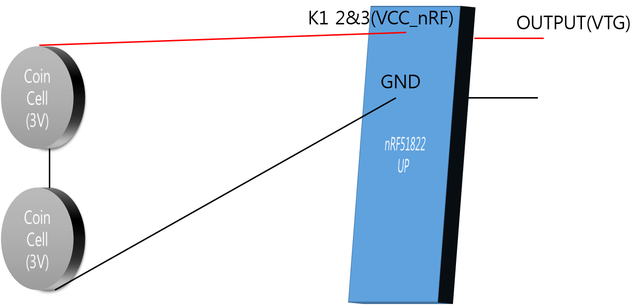
connection status

The battery is connected exactly as shown.

Without resistance, without capacitor

What is wrong with this approach?

Parents
  • I tried to configure the circuit again.

    image description

    I need 3.3V to nRF51822 and OLED.

    6V*(6.71M/(5.49M+6.71M)) = 3.3V

    If that minimum operating voltage of the OLED is 2.7V,

                                 Max    Input        Min     Input
                                 3.3V :   6V     =   2.7V :    x
    

    Therefore When the OLED is to use the minimum operating voltage, the input voltage is 4.9V.

          - Maximum voltage:   6V*(2.2M/(2.2M+10M)) = 1.082V
          - Minimum voltage: 4.9V*(2.2M/(2.2M+10M)) = 0.884V
          - ADC value at 6V   - 10 bit setup: 1.082/1.2*1023 = 992
          - ADC value at 4.9V - 10 bit setup: 0.884/1.2*1023 = 754
          - Usable ADC resolution - 10 bit setup: 992-754 = 238
    

    And source are as follows:

    #define ADC_REF_VOLTAGE_IN_MILLIVOLTS 1200
    #define ADC_PRE_SCALING_COMPENSATION 1
    #define DIODE_FWD_VOLT_DROP_MILLIVOLTS 270

    #define ADC_RESULT_IN_MILLI_VOLTS(ADC_VALUE)\

        ((((ADC_VALUE) * ADC_REF_VOLTAGE_IN_MILLIVOLTS) / 255) * ADC_PRE_SCALING_COMPENSATION)
    

    static void adc_init(void){	
    
    /* Enable interrupt on ADC sample ready event*/		
    NRF_ADC->INTENSET = ADC_INTENSET_END_Msk;   
    sd_nvic_SetPriority(ADC_IRQn, NRF_APP_PRIORITY_LOW);  
    sd_nvic_EnableIRQ(ADC_IRQn);
    
    NRF_ADC->CONFIG	= (ADC_CONFIG_EXTREFSEL_None << ADC_CONFIG_EXTREFSEL_Pos) /* Bits 17..16 : ADC external reference pin selection. */
    								| (ADC_CONFIG_PSEL_AnalogInput1<< ADC_CONFIG_PSEL_Pos)					/*!< Use analog input 1 as analog input. */
    								| (ADC_CONFIG_REFSEL_VBG << ADC_CONFIG_REFSEL_Pos)							/*!< Use internal 1.2V bandgap voltage as reference for conversion. */
    								| (ADC_CONFIG_INPSEL_AnalogInputNoPrescaling<< ADC_CONFIG_INPSEL_Pos) /*!< Analog input specified by PSEL with no prescaling used as input for the conversion. */
    								| (ADC_CONFIG_RES_10bit << ADC_CONFIG_RES_Pos);									/*!< 10bit ADC resolution. */ 
    
    /* Enable ADC*/
    NRF_ADC->ENABLE = ADC_ENABLE_ENABLE_Enabled;	           }
    

    void ADC_IRQHandler(void){
    uint8_t     adc_result;
    uint16_t    batt_lvl_in_milli_volts;
     int percent;
    
    /* Clear dataready event */
    NRF_ADC->EVENTS_END = 0;	
    
    adc_result = (NRF_ADC->RESULT);
    batt_lvl_in_milli_volts  = ADC_RESULT_IN_MILLI_VOLTS(adc_result)+DIODE_FWD_VOLT_DROP_MILLIVOLTS;
    percent = battery_level_in_pe
    
    
    NRF_ADC->TASKS_STOP = 1;


    //Release the external crystal
    sd_clock_hfclk_release();              }	
    

    Would not have a problem with as above?

    I wonder whether even such a way as above.

Reply
  • I tried to configure the circuit again.

    image description

    I need 3.3V to nRF51822 and OLED.

    6V*(6.71M/(5.49M+6.71M)) = 3.3V

    If that minimum operating voltage of the OLED is 2.7V,

                                 Max    Input        Min     Input
                                 3.3V :   6V     =   2.7V :    x
    

    Therefore When the OLED is to use the minimum operating voltage, the input voltage is 4.9V.

          - Maximum voltage:   6V*(2.2M/(2.2M+10M)) = 1.082V
          - Minimum voltage: 4.9V*(2.2M/(2.2M+10M)) = 0.884V
          - ADC value at 6V   - 10 bit setup: 1.082/1.2*1023 = 992
          - ADC value at 4.9V - 10 bit setup: 0.884/1.2*1023 = 754
          - Usable ADC resolution - 10 bit setup: 992-754 = 238
    

    And source are as follows:

    #define ADC_REF_VOLTAGE_IN_MILLIVOLTS 1200
    #define ADC_PRE_SCALING_COMPENSATION 1
    #define DIODE_FWD_VOLT_DROP_MILLIVOLTS 270

    #define ADC_RESULT_IN_MILLI_VOLTS(ADC_VALUE)\

        ((((ADC_VALUE) * ADC_REF_VOLTAGE_IN_MILLIVOLTS) / 255) * ADC_PRE_SCALING_COMPENSATION)
    

    static void adc_init(void){	
    
    /* Enable interrupt on ADC sample ready event*/		
    NRF_ADC->INTENSET = ADC_INTENSET_END_Msk;   
    sd_nvic_SetPriority(ADC_IRQn, NRF_APP_PRIORITY_LOW);  
    sd_nvic_EnableIRQ(ADC_IRQn);
    
    NRF_ADC->CONFIG	= (ADC_CONFIG_EXTREFSEL_None << ADC_CONFIG_EXTREFSEL_Pos) /* Bits 17..16 : ADC external reference pin selection. */
    								| (ADC_CONFIG_PSEL_AnalogInput1<< ADC_CONFIG_PSEL_Pos)					/*!< Use analog input 1 as analog input. */
    								| (ADC_CONFIG_REFSEL_VBG << ADC_CONFIG_REFSEL_Pos)							/*!< Use internal 1.2V bandgap voltage as reference for conversion. */
    								| (ADC_CONFIG_INPSEL_AnalogInputNoPrescaling<< ADC_CONFIG_INPSEL_Pos) /*!< Analog input specified by PSEL with no prescaling used as input for the conversion. */
    								| (ADC_CONFIG_RES_10bit << ADC_CONFIG_RES_Pos);									/*!< 10bit ADC resolution. */ 
    
    /* Enable ADC*/
    NRF_ADC->ENABLE = ADC_ENABLE_ENABLE_Enabled;	           }
    

    void ADC_IRQHandler(void){
    uint8_t     adc_result;
    uint16_t    batt_lvl_in_milli_volts;
     int percent;
    
    /* Clear dataready event */
    NRF_ADC->EVENTS_END = 0;	
    
    adc_result = (NRF_ADC->RESULT);
    batt_lvl_in_milli_volts  = ADC_RESULT_IN_MILLI_VOLTS(adc_result)+DIODE_FWD_VOLT_DROP_MILLIVOLTS;
    percent = battery_level_in_pe
    
    
    NRF_ADC->TASKS_STOP = 1;


    //Release the external crystal
    sd_clock_hfclk_release();              }	
    

    Would not have a problem with as above?

    I wonder whether even such a way as above.

Children
Related