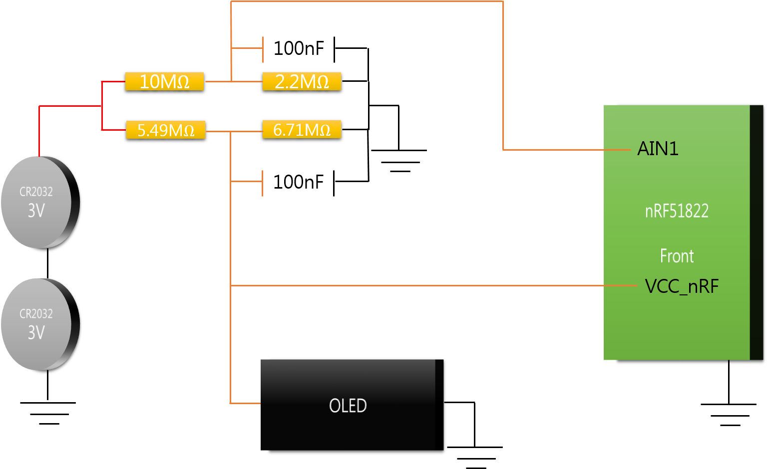
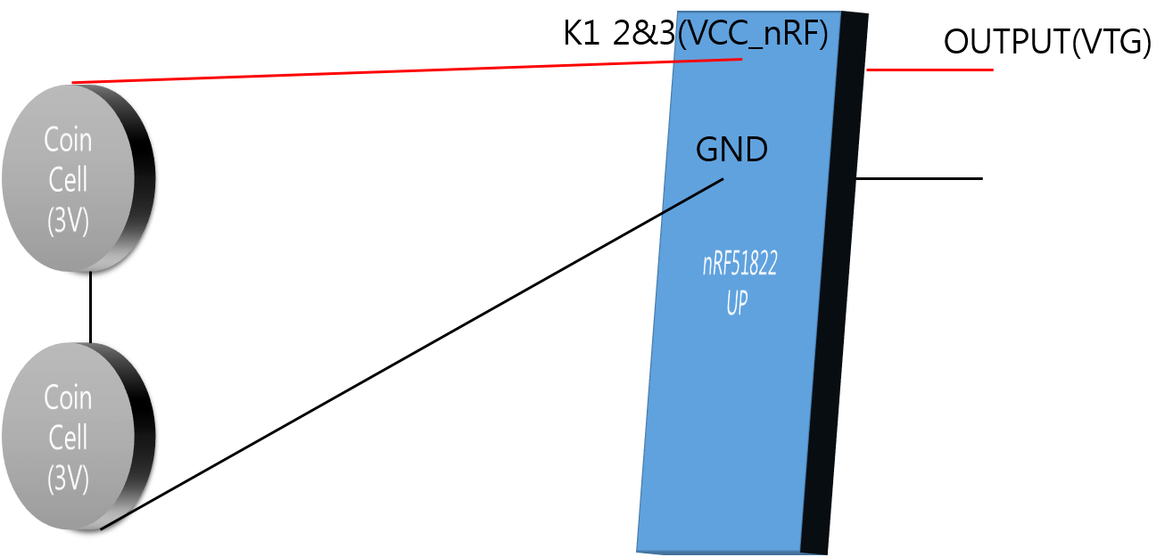
This post is older than 2 years and might not be relevant anymore
More Info: Consider searching for newer posts

I want to measurement Battery level.

(I use nrf51822)

I use two 3V batteries in series.

Therefore Input Voltage of My Circuit is 6V.

My own source was coded as a collection of information.

Oh, by the way, I used a battery is Cr2032 Coin Cell.

Looking for information on a coin cell is found in the link below.

Coin Cell Link

Is there anything wrong with my source?

Um, but uses a lot of battery, the battery is still in 100% condition.

What mistakes did I do?

I need help. please!


  /**< Reference voltage (in milli volts) used by ADC while doing conversion. */

  #define ADC_REF_VOLTAGE_IN_MILLIVOLTS        1200                    
  
  /**< The ADC is configured to use VDD with 1/3 prescaling as input. And hence the result of                       
        conversion is to be multiplied by 3 to get the actual value of the battery voltage.*/
                                
   #define ADC_PRE_SCALING_COMPENSATION         3                                          
  
  /**< Typical forward voltage drop of the diode (Part no: SD103ATW-7-F) that is connected in 
         series with the voltage supply. This is the voltage drop when the forward current is 1mA. 
         Source: Data sheet of 'SURFACE MOUNT SCHOTTKY BARRIER DIODE ARRAY' available at 
         www.diodes.com. */

  #define DIODE_FWD_VOLT_DROP_MILLIVOLTS       270                                        
  #define ADC_RESULT_IN_MILLI_VOLTS(ADC_VALUE)\
        ((((ADC_VALUE) * ADC_REF_VOLTAGE_IN_MILLIVOLTS) / 255) * ADC_PRE_SCALING_COMPENSATION)


static void adc_init(void)
{	
	
	/* Enable interrupt on ADC sample ready event*/		
	NRF_ADC->INTENSET = ADC_INTENSET_END_Msk;   
	sd_nvic_SetPriority(ADC_IRQn, NRF_APP_PRIORITY_LOW);  
	sd_nvic_EnableIRQ(ADC_IRQn);
	
	NRF_ADC->CONFIG	= (ADC_CONFIG_EXTREFSEL_None << ADC_CONFIG_EXTREFSEL_Pos) /* Bits 17..16 : ADC external reference pin selection. */
									| (ADC_CONFIG_PSEL_Disabled << ADC_CONFIG_PSEL_Pos)					/*!< Use analog input 2 as analog input. */
									| (ADC_CONFIG_REFSEL_VBG << ADC_CONFIG_REFSEL_Pos)							/*!< Use internal 1.2V bandgap voltage as reference for conversion. */
									| (ADC_CONFIG_INPSEL_SupplyOneThirdPrescaling << ADC_CONFIG_INPSEL_Pos) /*!< Analog input specified by PSEL with no prescaling used as input for the conversion. */
									| (ADC_CONFIG_RES_8bit << ADC_CONFIG_RES_Pos);									/*!< 8bit ADC resolution. */ 
	
	/* Enable ADC*/
	NRF_ADC->ENABLE = ADC_ENABLE_ENABLE_Enabled;
	
}


void ADC_IRQHandler(void)
{

    uint8_t     adc_result;
    uint16_t    batt_lvl_in_milli_volts;
    int percent;
	
	/* Clear dataready event */
    NRF_ADC->EVENTS_END = 0;	
  
	adc_result = (NRF_ADC->RESULT);
    batt_lvl_in_milli_volts  = ADC_RESULT_IN_MILLI_VOLTS(adc_result);
	percent = battery_level_in_percent(batt_lvl_in_milli_volts);
    NRF_ADC->TASKS_STOP = 1;
	
	//Release the external crystal
	sd_clock_hfclk_release();
}	

#Edit : 2015-04-13

Current connection status is shown in the figure below.

connection status

The battery is connected exactly as shown.

Without resistance, without capacitor

What is wrong with this approach?

  • Oh.. Sorry, but not yet understood.

    If the maximum value of the voltage entering the port is 3.6V and the voltage going to the other device 5V, What is the measurement method?

    I have understood the contents as follows:

    1. the voltage entering the board and another device is connected in parallel.

    2. The voltage is put into a board made of 3.6V using a resistor. (Divided by 3.6V and 2.4V.)

    3. If the voltage using the voltage drops, the voltage entering the board and another device (3.6V and 5V) will be the same is that ratio.

    4. Therefore, if I want to know the remaining capacity of the battery, measures the voltage entering the board.

    Did I understand the details are correct?

  • So, you would want to use a voltage divider at the input of the ADC to get as close to 0.6V as possible (Because of minimal current flow in to the ADC). You can check out this post to see how to make a voltage divider: devzone.nordicsemi.com/.../

    The post also refers to some example code. Note that this is the voltage going in to one of the ADC input pins on the chip, not the supply voltage (VDD).

    For the supply voltage (VDD) you would need to use a voltage regulator in order to lower the voltage to within the operating conditions specified in the nRF51822 Product Specification section 7.

  • I tried to configure the circuit again.

    image description

    I need 3.3V to nRF51822 and OLED.

    6V*(6.71M/(5.49M+6.71M)) = 3.3V

    If that minimum operating voltage of the OLED is 2.7V,

                                 Max    Input        Min     Input
                                 3.3V :   6V     =   2.7V :    x
    

    Therefore When the OLED is to use the minimum operating voltage, the input voltage is 4.9V.

          - Maximum voltage:   6V*(2.2M/(2.2M+10M)) = 1.082V
          - Minimum voltage: 4.9V*(2.2M/(2.2M+10M)) = 0.884V
          - ADC value at 6V   - 10 bit setup: 1.082/1.2*1023 = 992
          - ADC value at 4.9V - 10 bit setup: 0.884/1.2*1023 = 754
          - Usable ADC resolution - 10 bit setup: 992-754 = 238
    

    And source are as follows:

    #define ADC_REF_VOLTAGE_IN_MILLIVOLTS 1200
    #define ADC_PRE_SCALING_COMPENSATION 1
    #define DIODE_FWD_VOLT_DROP_MILLIVOLTS 270

    #define ADC_RESULT_IN_MILLI_VOLTS(ADC_VALUE)\

        ((((ADC_VALUE) * ADC_REF_VOLTAGE_IN_MILLIVOLTS) / 255) * ADC_PRE_SCALING_COMPENSATION)
    

    static void adc_init(void){	
    
    /* Enable interrupt on ADC sample ready event*/		
    NRF_ADC->INTENSET = ADC_INTENSET_END_Msk;   
    sd_nvic_SetPriority(ADC_IRQn, NRF_APP_PRIORITY_LOW);  
    sd_nvic_EnableIRQ(ADC_IRQn);
    
    NRF_ADC->CONFIG	= (ADC_CONFIG_EXTREFSEL_None << ADC_CONFIG_EXTREFSEL_Pos) /* Bits 17..16 : ADC external reference pin selection. */
    								| (ADC_CONFIG_PSEL_AnalogInput1<< ADC_CONFIG_PSEL_Pos)					/*!< Use analog input 1 as analog input. */
    								| (ADC_CONFIG_REFSEL_VBG << ADC_CONFIG_REFSEL_Pos)							/*!< Use internal 1.2V bandgap voltage as reference for conversion. */
    								| (ADC_CONFIG_INPSEL_AnalogInputNoPrescaling<< ADC_CONFIG_INPSEL_Pos) /*!< Analog input specified by PSEL with no prescaling used as input for the conversion. */
    								| (ADC_CONFIG_RES_10bit << ADC_CONFIG_RES_Pos);									/*!< 10bit ADC resolution. */ 
    
    /* Enable ADC*/
    NRF_ADC->ENABLE = ADC_ENABLE_ENABLE_Enabled;	           }
    

    void ADC_IRQHandler(void){
    uint8_t     adc_result;
    uint16_t    batt_lvl_in_milli_volts;
     int percent;
    
    /* Clear dataready event */
    NRF_ADC->EVENTS_END = 0;	
    
    adc_result = (NRF_ADC->RESULT);
    batt_lvl_in_milli_volts  = ADC_RESULT_IN_MILLI_VOLTS(adc_result)+DIODE_FWD_VOLT_DROP_MILLIVOLTS;
    percent = battery_level_in_pe
    
    
    NRF_ADC->TASKS_STOP = 1;


    //Release the external crystal
    sd_clock_hfclk_release();              }	
    

    Would not have a problem with as above?

    I wonder whether even such a way as above.

    1. Why are you using 6V if both the OLED and the nRF51 are running on 3.3V?

    2. The AIN1 voltage divider is correct.

    3. You can not use a voltage divider to lower the voltage for the VCC of nRF51. You have to use a voltage regulator: en.wikipedia.org/.../Voltage_regulator . Have a look at the 5.49MOhm resistor: 6V / 5.49MOhm = 1.1uA. The resistor is too large to supply enough current to the nRF51. The nRF51 requires at least 16 mA when using the radio. So, you would need to lower the resistor values by a factor of tens of thousands. This would cause the resistors to burn up several mAmps all the time.

  • I use CR2032 Coin cell(3v).

    but Working voltage of OLED is 3.3V.

    So I Used Two Coin cell.

    Would you say that to me 5.49 (Mega Ohm) and 6.71 (Mega Ohm) is unnecessary?

    And change to a lower resistance than it is now, I could add a voltage regulator?(In that part)

Related