
Hi all,
I am working on a project with an Adafruit ItsyBitsy that uses and nRF52840 chip, and I am having a bit of trouble with getting the timers to work accurately. Basically what I want to do is to have a task completed once per second, and I was planning on using a software timer to do so. I have attached an image of the sort of sawtooth wave that I want to create: 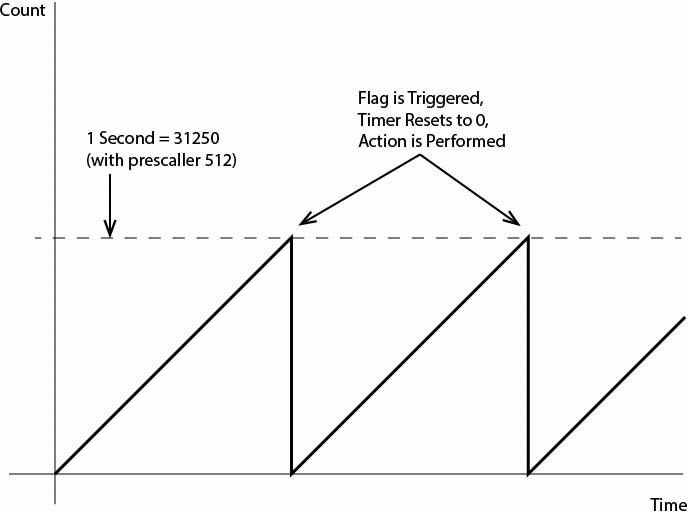
I have been reading through the data sheet of the NRF52840 and some other examples that people have done. It seems like this should be perfectly doable with Timer2. However, when I try to execute it in code I am getting a strange output. I have attached my code, here, as well (sorry it is in Arduino's IDE, but mostly I am manually setting registers in a very basic C++ kind of way).
#include <bluefruit.h>

/* NRF Timer Demo
 *  Loops the timer at 1 second
 *  Prints a value every 60 seconds
 *
 */

// Defining Timer2 Registers
static const unsigned int Timer_2_base = 0x4000A000;
enum Registers
{
  TASKS_START = 0x000, // Start Timer
  TASKS_STOP = 0x004, // Stop Timer
  TASKS_COUNT = 0x008, // Increment Timer (Counter mode only)
  TASKS_CLEAR = 0x00C, // Clear time
  TASKS_SHUTDOWN = 0x010, // Shut down timerDeprecated
  TASKS_CAPTURE_0 = 0x040, // Capture Timer value to CC[0] register
  TASKS_CAPTURE_1 = 0x044, // Capture Timer value to CC[1] register
  TASKS_CAPTURE_2 = 0x048, // Capture Timer value to CC[2] register
  TASKS_CAPTURE_3 = 0x04C, // Capture Timer value to CC[3] register
  TASKS_CAPTURE_4 = 0x050, // Capture Timer value to CC[4] register
  TASKS_CAPTURE_5 = 0x054, // Capture Timer value to CC[5] register
  EVENTS_COMPARE_0 = 0x140, // Compare event on CC[0] match
  EVENTS_COMPARE_1 = 0x144, // Compare event on CC[1] match
  EVENTS_COMPARE_2 = 0x148, // Compare event on CC[2] match
  EVENTS_COMPARE_3 = 0x14C, // Compare event on CC[3] match
  EVENTS_COMPARE_4 = 0x150, // Compare event on CC[4] match
  EVENTS_COMPARE_5 = 0x154, // Compare event on CC[5] match
  SHORTS = 0x200, // Shortcuts between local events and tasks
  INTENSET = 0x304, // Enable interrupt
  INTENCLR = 0x308, // Disable interrupt
  MODE = 0x504, // Timer mode selection
  BITMODE = 0x508, // Configure the number of bits used by the TIMER
  PRESCALER = 0x510, // Timer prescaler register
  CC_0 = 0x540, // Capture/Compare register 0
  CC_1 = 0x544, // Capture/Compare register 1
  CC_2 = 0x548, // Capture/Compare register 2
  CC_3 = 0x54C, // Capture/Compare register 3
  CC_4 = 0x550, // Capture/Compare register 4
  CC_5 = 0x554 // Capture/Compare register 5
};

// Inline Register functions
inline volatile uint8_t *regAddress (Registers reg){
  return reinterpret_cast<volatile
        uint8_t*>(Timer_2_base + reg);
}
inline uint8_t regRead(Registers reg){
  return *regAddress(reg);
}
inline void regWrite(Registers reg, uint8_t value){
  *regAddress(reg) = value;
}

// Parameters
const int ledPin =  7;
const uint16_t max_value = 31250;
const uint32_t interupt_activator = 0x0001000;
volatile bool ledState = LOW;
int samples_taken = 0;
int passes_completed = 0;

void setup() {
  Serial.begin(9600);
  // set the digital pin as output:
  pinMode(ledPin, OUTPUT);
  digitalWrite(ledPin, ledState);

  regWrite(TASKS_STOP, 1);    // Stop TIMER2
  regWrite(MODE, 0);          // Set the timer in Counter Mode
  regWrite(TASKS_CLEAR, 1);   // clear the task first to be usable for later
  regWrite(BITMODE, 0);       // Set counter to 32 bit resolution
  regWrite(PRESCALER, 9);     // Set prescaler (2^n). Prescaller of 9 gives 512
  regWrite(CC_0, max_value);      // set the maximum timer value (31250 = 1 second)
  regWrite(INTENSET, interupt_activator);      // Enabling the interupt for maximum value being reached

  regWrite(TASKS_START, 1);   // Start TIMER2
  Serial.println("Timer configured");
}

void loop(){
  if(regRead(EVENTS_COMPARE_0) == 1){
    regWrite(TASKS_CLEAR, 1);       // Resetting the timer to 0
    regWrite(EVENTS_COMPARE_0, 0);    // Clearing the events compare bit
    ledState = !ledState;          //Set LED
    samples_taken += 1;
  }

  if(samples_taken > 0){
    samples_taken = 0;
    passes_completed += 1;
    Serial.print(passes_completed);
    Serial.print(", ");
    Serial.println(millis());
  }
  digitalWrite(ledPin, ledState);
}
Based on my understanding of the system, this should create a 1 second looping timer, but it does not. Instead, it creates an ~147 ms looping timer. My next step was to try changing the maximum value, but the time duration seems to be random. For example around 5,800 gives 0.8 seconds, and around 63,000 gives 1.5 seconds. Am I misinterpreting what the CC[0] register means? Also, in the data sheet, it says that the INTENSET enables an interrupt. Does anyone know the pointer for that? I have tried setting up a proper ISR, but it doesn't seem to do anything. I may be running into issues with the Arduino IDE mask. Any help, here would be much appreciated! Thank you!!

