This post is older than 2 years and might not be relevant anymore
More Info: Consider searching for newer posts

SPI not operating correctly at high speeds

Hello,

I'm having issues getting my SPI to work at high transfer speeds.
I have my pins configured to have high drive.

SPI is set to MSB first, Mode 0. 
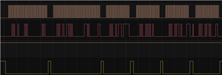
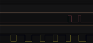
Colors:

Brown = SCK

Red = MOSI

Orange = MISO

Yellow = CS

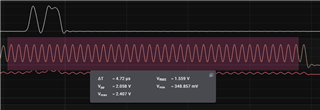
This is a transaction on 125kbps, working  fine.

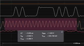
This is at 500kbps, not getting all clock pulses.

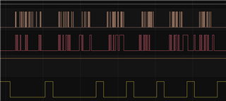
This is at 8Mbps and yeah... nothing here but the chip select.

Can anyone help me getting this work at higher speeds?

Kind regards.

Parents
  • Hi Tom

    Seeing as the SCK signal seems to be the source of the problem here, have you tried switching this to be any other GPIO, to make sure that it isn't specific to that one pin (just in case there is any issues with the soldering or connection on that GPIO.

    Best regards,

    Simon

  • This is clock on Pin 8, still the same.

    On 52832 DK, pin 7 is a CTS signal of debug UART - this may cause an issue.

    I have turned off the UART debug output in the CMSIS config wizzard. I always use the RTT option.

    Pin 11 also looks the same.

  • Sorry to be pedantic, but standard drive will not look the same as high drive on your scope, even with significant wire lengths; if it does look the same, then high drive has not been applied correctly. Perhaps review this setting again, the high drive must be set after any SPI init otherwise it will be overwritten by that SPI init.

    Also place one channel of the scope on SCK at the Nordic end with the scope Gnd on Nordic Gnd, and place a second scope channel on SCK (same signal) on the remote device end with that second scope Gnd at the Gnd on the remote device end. Capture the trace and post them here. They will not look the same if the scope probes are placed correctly even though they are connected by a 6 inch jumper.

Reply
  • Sorry to be pedantic, but standard drive will not look the same as high drive on your scope, even with significant wire lengths; if it does look the same, then high drive has not been applied correctly. Perhaps review this setting again, the high drive must be set after any SPI init otherwise it will be overwritten by that SPI init.

    Also place one channel of the scope on SCK at the Nordic end with the scope Gnd on Nordic Gnd, and place a second scope channel on SCK (same signal) on the remote device end with that second scope Gnd at the Gnd on the remote device end. Capture the trace and post them here. They will not look the same if the scope probes are placed correctly even though they are connected by a 6 inch jumper.

Children
No Data
Related