This post is older than 2 years and might not be relevant anymore
More Info: Consider searching for newer posts

Adc pin getting different results in during charging of board.

Hi,
I am working with custom board in that, trying to read NTC sensor value using 2 (NTC+ and NTC-) ADC pins. Applied Steinhart formula to convert temperature.
In that, After charging board unplugged and trying to read then, I am getting it's 37,36 value of temperature. But during charging It's I am getting 0 temperature value.

I have see during charging adc pin of (ntc+) = -2 around value and (Ntc-) = around 50 value get.
After charging unplugged and checked in that (ntc+) = 700 around and (ntc-) = 350 around value I am getting.
I have applied SAADC code from example/peripheral and configuration is internal reference voltage 0.6 and gain 1/6.
And Input charging is 5V. I don't know why I am getting 0 during Charging mode.
Can you please help?

And also, I am not getting proper temperature value based on heat condition Can anyone know for this?  please help 

Parents
  • Hello,

    I am working with custom board in that, trying to read NTC sensor value using 2 (NTC+ and NTC-) ADC pins.

    I understand that you are using a differential NTC sensor to measure temperature, so far so good.
    Is it a particular NTC sensor you are working with, do you have its data sheet?

    After charging board unplugged and trying to read then, I am getting it's 37,36 value of temperature. But during charging It's I am getting 0 temperature value.

    Here things get a little more unclear. Could you please elaborate what you mean when you say "during charging" here, do you mean when the board is powered by USB as opposed to the coin cell battery, or what?
    Which pins are you using for the measurements, and what is your SAADC and Channel's configuration? If you could provide a schematic or other document to indicate how you have connected your custom board with the NTC sensors, that would be helpful.
    Please use the "Insert -> Code" option if you are going to share code.

    I have see during charging adc pin of (ntc+) = -2 around value and (Ntc-) = around 50 value get.
    After charging unplugged and checked in that (ntc+) = 700 around and (ntc-) = 350 around value I am getting.
    I have applied SAADC code from example/peripheral and configuration is internal reference voltage 0.6 and gain 1/6.
    And Input charging is 5V. I don't know why I am getting 0 during Charging mode.
    Can you please help?

    I am not sure I have understood the situation you refer to when you say that you are charging, but seeing as you mention 5 V input when charging I suspect that you refer to the board being powered by USB?

    Applied Steinhart formula to convert temperature.

    Are you first converting your samples to voltages, before inputting them to the Steinhart forumla? Or, are you providing the steinhart forumla with raw SAADC outputs?

    Looking forward to resolve this issue together,

    Best regards,
    Karl

  • Hi, Karl thanks for the reply,

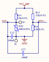
    I have a wrist band and that has an NTC sensor and NTC+  and NTC- are given in AIN1 and AIN2 (NRF52832), and charge band using USB(5V). I have attached the NTC screenshot here.
    I have read the SAADC data and applied steinhart formula.
    I have attached the file for code.
    If charging a band using USB and the same time if I read value then getting 0 value but after unplugged USB and read then different value of temperature.
    I am direct given the SAADC raw value to the Steinhart formula. 
    And based on heat not changed value of temperature also.
    Please suggest I am in the right direction or not?


    /**
     * Copyright (c) 2014 - 2017, Nordic Semiconductor ASA
     * 
     * All rights reserved.
     * 
     * Redistribution and use in source and binary forms, with or without modification,
     * are permitted provided that the following conditions are met:
     * 
     * 1. Redistributions of source code must retain the above copyright notice, this
     *    list of conditions and the following disclaimer.
     * 
     * 2. Redistributions in binary form, except as embedded into a Nordic
     *    Semiconductor ASA integrated circuit in a product or a software update for
     *    such product, must reproduce the above copyright notice, this list of
     *    conditions and the following disclaimer in the documentation and/or other
     *    materials provided with the distribution.
     * 
     * 3. Neither the name of Nordic Semiconductor ASA nor the names of its
     *    contributors may be used to endorse or promote products derived from this
     *    software without specific prior written permission.
     * 
     * 4. This software, with or without modification, must only be used with a
     *    Nordic Semiconductor ASA integrated circuit.
     * 
     * 5. Any software provided in binary form under this license must not be reverse
     *    engineered, decompiled, modified and/or disassembled.
     * 
     * THIS SOFTWARE IS PROVIDED BY NORDIC SEMICONDUCTOR ASA "AS IS" AND ANY EXPRESS
     * OR IMPLIED WARRANTIES, INCLUDING, BUT NOT LIMITED TO, THE IMPLIED WARRANTIES
     * OF MERCHANTABILITY, NONINFRINGEMENT, AND FITNESS FOR A PARTICULAR PURPOSE ARE
     * DISCLAIMED. IN NO EVENT SHALL NORDIC SEMICONDUCTOR ASA OR CONTRIBUTORS BE
     * LIABLE FOR ANY DIRECT, INDIRECT, INCIDENTAL, SPECIAL, EXEMPLARY, OR
     * CONSEQUENTIAL DAMAGES (INCLUDING, BUT NOT LIMITED TO, PROCUREMENT OF SUBSTITUTE
     * GOODS OR SERVICES; LOSS OF USE, DATA, OR PROFITS; OR BUSINESS INTERRUPTION)
     * HOWEVER CAUSED AND ON ANY THEORY OF LIABILITY, WHETHER IN CONTRACT, STRICT
     * LIABILITY, OR TORT (INCLUDING NEGLIGENCE OR OTHERWISE) ARISING IN ANY WAY OUT
     * OF THE USE OF THIS SOFTWARE, EVEN IF ADVISED OF THE POSSIBILITY OF SUCH DAMAGE.
     * 
     */
    /** @file
     *
     * @defgroup ble_sdk_app_beacon_main main.c
     * @{
     * @ingroup ble_sdk_app_beacon
     * @brief Beacon Transmitter Sample Application main file.
     *
     * This file contains the source code for an Beacon transmitter sample application.
     */
    
    #include <stdbool.h>
    #include <stdint.h>
    #include <string.h>
    #include "nordic_common.h"
    #include "bsp.h"
    #include "nrf_soc.h"
    #include "nrf_sdh.h"
    #include "nrf_sdh_ble.h"
    #include "ble_advdata.h"
    #include "app_timer.h"
    #include "nrf_log.h"
    #include "nrf_log_ctrl.h"
    #include "nrf_log_default_backends.h"
    #include "nrf_delay.h"
    #include "math.h"
    #include "app_pwm.h"
    #include "nrf_drv_saadc.h"
    
    #define APP_BLE_CONN_CFG_TAG            1                                 /**< A tag identifying the SoftDevice BLE configuration. */
    
    #define NON_CONNECTABLE_ADV_INTERVAL    MSEC_TO_UNITS(20, UNIT_0_625_MS) /**< The advertising interval for non-connectable advertisement (100 ms). This value can vary between 100ms to 10.24s). */
    #define DEVICE_NAME                     "SDA"                             /**< Name of device. Will be included in the advertising data. */
    #define APP_BEACON_INFO_LENGTH          0x17                              /**< Total length of information advertised by the Beacon. */
    #define APP_ADV_DATA_LENGTH             0x15                              /**< Length of manufacturer specific data in the advertisement. */
    #define APP_DEVICE_TYPE                 0x02                              /**< 0x02 refers to Beacon. */
    #define APP_MEASURED_RSSI               0xC3                              /**< The Beacon's measured RSSI at 1 meter distance in dBm. */
    #define APP_COMPANY_IDENTIFIER          0x0059                            /**< Company identifier for Nordic Semiconductor ASA. as per www.bluetooth.org. */
    #define APP_MAJOR_VALUE                 0x01, 0x02                        /**< Major value used to identify Beacons. */
    #define APP_MINOR_VALUE                 0x03, 0x04                        /**< Minor value used to identify Beacons. */
    #define APP_BEACON_UUID                 0x01, 0x12, 0x23, 0x34, \
                                            0x45, 0x56, 0x67, 0x78, \
                                            0x89, 0x9a, 0xab, 0xbc, \
                                            0xcd, 0xde, 0xef, 0xf0            /**< Proprietary UUID for Beacon. */
    
    #define DEAD_BEEF                       0xDEADBEEF                        /**< Value used as error code on stack dump, can be used to identify stack location on stack unwind. */
    
    #if defined(USE_UICR_FOR_MAJ_MIN_VALUES)
    #define MAJ_VAL_OFFSET_IN_BEACON_INFO   18                                /**< Position of the MSB of the Major Value in m_beacon_info array. */
    #define UICR_ADDRESS                    0x10001080                        /**< Address of the UICR register used by this example. The major and minor versions to be encoded into the advertising data will be picked up from this location. */
    #endif
    
    #define SCAN_DURATION_WITELIST 			0x00							  /**< Duration of the scanning in units of 10 milliseconds. */
    #define NRF_BLE_SCAN_SCAN_INTERVAL		0x0032
    #define NRF_BLE_SCAN_SCAN_DURATION 		0
    #define NRF_BLE_SCAN_SCAN_WINDOW		0x0019
    
    #define BRODCASTING_INTERVAL     		APP_TIMER_TICKS(5000)             /**< Brodcast data timer interval (ticks). */
    #define MOTOR_BUZZER_DATA_INTERVAL     	APP_TIMER_TICKS(1000)             /**< Motor and buzzer control timer interval (ticks). */
    
    #define BT_ADDR_LEN 					0x06
    #define LIST_LEN						10								  /**< Device List Length*/
    #define SLS_COMPANY_ID					0x534C
    #define MANUFACTURE_DATA_LEN			4
    /** @brief Advertising set handle not set. */
    #define BLE_GAP_ADV_SET_HANDLE_NOT_SET (0xFF)
    #define APP_BLE_OBSERVER_PRIO           0
    
    #define ADC_REF_VOLTAGE_IN_MILLIVOLTS   600                                     /**< Reference voltage (in milli volts) used by ADC while doing conversion. */
    #define ADC_PRE_SCALING_COMPENSATION    6                                       /**< The ADC is configured to use VDD with 1/3 prescaling as input. And hence the result of conversion is to be multiplied by 3 to get the actual value of the battery voltage.*/
    #define DIODE_FWD_VOLT_DROP_MILLIVOLTS  270                                     /**< Typical forward voltage drop of the diode . */
    #define ADC_RES_10BIT                   1024                                    /**< Maximum digital value for 10-bit ADC conversion. */
    
    /**@brief Macro to convert the result of ADC conversion in millivolts.
     *
     * @param[in]  ADC_VALUE   ADC result.
     *
     * @retval     Result converted to millivolts.
     */
    #define ADC_RESULT_IN_MILLI_VOLTS(ADC_VALUE)\
            ((((ADC_VALUE) * ADC_REF_VOLTAGE_IN_MILLIVOLTS) / ADC_RES_10BIT) * ADC_PRE_SCALING_COMPENSATION)
    
    
    APP_TIMER_DEF(proximity_app_timer_id); 					  				  /**< Proximity app timer. */
    APP_TIMER_DEF(Brodcast_data_timer_id); 					  				  /**< brodcasting data */
    APP_TIMER_DEF(motor_buzzer_data_timer_id);								  /**< Motor and buzzer data */
    NRF_BLE_SCAN_DEF(m_scan);                                 /**< Scanning Module instance. */
    
    static ble_gap_scan_params_t m_scan_param =               /**< Scan parameters requested for scanning and connection. */
    {
        .active        = 1,
        .interval      = NRF_BLE_SCAN_SCAN_INTERVAL,
        .window        = NRF_BLE_SCAN_SCAN_WINDOW,
        .timeout       = NRF_BLE_SCAN_SCAN_DURATION,
        #if (NRF_SD_BLE_API_VERSION <= 2)
            .selective   = 0,
            .p_whitelist = NULL,
        #endif
        #if (NRF_SD_BLE_API_VERSION >= 3)
            .use_whitelist = 0,
        #endif
    };
    
    
    /**@brief Variable length data encapsulation in terms of length and pointer to data */
    typedef struct
    {
        uint8_t * p_data;   /**< Pointer to data. */
        uint16_t  data_len; /**< Length of data. */
    }data_t;
    
    static bool scan_evt = false;
    
    static uint8_t scan_result_not_avail_count = 0U;
    
    
    static ble_gap_adv_params_t m_adv_params;                                 /**< Parameters to be passed to the stack when starting advertising. */
    
    static uint8_t              m_enc_advdata[BLE_GAP_ADV_MAX_SIZE];  /**< Buffer for storing an encoded advertising set. */
    
    static uint8_t manufacure_adv_data[MANUFACTURE_DATA_LEN] = {0x01, 0x3E, 0x46, 0x82};
    int red_device = 0;
    int8_t *payload = NULL;
    int g_payload_index = 11;
    static uint8_t motor_buzzer_control = 0;
    APP_PWM_INSTANCE(PWM1,1);                   // Create the instance "PWM1" using TIMER1.
    static volatile bool ready_flag;            // A flag indicating PWM status.
    
    #define SAMPLES_IN_BUFFER 2
    volatile uint8_t state = 1;
    
    static const nrf_drv_timer_t m_timer = NRF_DRV_TIMER_INSTANCE(2);
    static nrf_saadc_value_t     m_buffer_pool[2][SAMPLES_IN_BUFFER];
    static nrf_ppi_channel_t     m_ppi_channel;
    static uint32_t              m_adc_evt_counter;
    static float steinhart;
    #if 0
    static uint8_t m_beacon_info[APP_BEACON_INFO_LENGTH] =                    /**< Information advertised by the Beacon. */
    {
        APP_DEVICE_TYPE,     // Manufacturer specific information. Specifies the device type in this
                             // implementation.
        APP_ADV_DATA_LENGTH, // Manufacturer specific information. Specifies the length of the
                             // manufacturer specific data in this implementation.
        APP_BEACON_UUID,     // 128 bit UUID value.
        APP_MAJOR_VALUE,     // Major arbitrary value that can be used to distinguish between Beacons.
        APP_MINOR_VALUE,     // Minor arbitrary value that can be used to distinguish between Beacons.
        APP_MEASURED_RSSI    // Manufacturer specific information. The Beacon's measured TX power in
                             // this implementation.
    };
    #endif
    
    /**@brief Callback function for asserts in the SoftDevice.
     *
     * @details This function will be called in case of an assert in the SoftDevice.
     *
     * @warning This handler is an example only and does not fit a final product. You need to analyze
     *          how your product is supposed to react in case of Assert.
     * @warning On assert from the SoftDevice, the system can only recover on reset.
     *
     * @param[in]   line_num   Line number of the failing ASSERT call.
     * @param[in]   file_name  File name of the failing ASSERT call.
     */
    void assert_nrf_callback(uint16_t line_num, const uint8_t * p_file_name)
    {
        app_error_handler(DEAD_BEEF, line_num, p_file_name);
    }
    
    /**@brief Function for the GAP initialization.
     *
     * @details This function will set up all the necessary GAP (Generic Access Profile) parameters of
     *          the device. It also sets the permissions and appearance.
     */
    static void gap_params_init(void)
    {
        uint32_t                err_code;
        ble_gap_conn_sec_mode_t sec_mode;
    
        BLE_GAP_CONN_SEC_MODE_SET_OPEN(&sec_mode);
    
        err_code = sd_ble_gap_device_name_set(&sec_mode,
                                              (const uint8_t *) DEVICE_NAME,
                                              strlen(DEVICE_NAME));
        APP_ERROR_CHECK(err_code);
    }
    
    static void motor_buzzer_handler(void * p_context)
    {
    	if(motor_buzzer_control == 1){
    
    	}
    	else{
    
    	}
    }
    
    /**@brief Function for initializing the Advertising functionality.
     *
     * @details Encodes the required advertising data and passes it to the stack.
     *          Also builds a structure to be passed to the stack when starting advertising.
     */	
    static void advertising_init(void)
    {
        uint32_t      err_code;
        ble_advdata_t advdata;
        uint8_t       flags = BLE_GAP_ADV_FLAG_BR_EDR_NOT_SUPPORTED;
    	ble_advdata_manuf_data_t manuf_specific_data;
    /*#if defined(USE_UICR_FOR_MAJ_MIN_VALUES)
        // If USE_UICR_FOR_MAJ_MIN_VALUES is defined, the major and minor values will be read from the
        // UICR instead of using the default values. The major and minor values obtained from the UICR
        // are encoded into advertising data in big endian order (MSB First).
        // To set the UICR used by this example to a desired value, write to the address 0x10001080
        // using the nrfjprog tool. The command to be used is as follows.
        // nrfjprog --snr <Segger-chip-Serial-Number> --memwr 0x10001080 --val <your major/minor value>
        // For example, for a major value and minor value of 0xabcd and 0x0102 respectively, the
        // the following command should be used.
        // nrfjprog --snr <Segger-chip-Serial-Number> --memwr 0x10001080 --val 0xabcd0102
        uint16_t major_value = ((*(uint32_t *)UICR_ADDRESS) & 0xFFFF0000) >> 16;
        uint16_t minor_value = ((*(uint32_t *)UICR_ADDRESS) & 0x0000FFFF);
    
        uint8_t index = MAJ_VAL_OFFSET_IN_BEACON_INFO;
    
        m_beacon_info[index++] = MSB_16(major_value);
        m_beacon_info[index++] = LSB_16(major_value);
    
        m_beacon_info[index++] = MSB_16(minor_value);
        m_beacon_info[index++] = LSB_16(minor_value);
    #endif
    
        manuf_specific_data.data.p_data = (uint8_t *) m_beacon_info;
        manuf_specific_data.data.size   = APP_BEACON_INFO_LENGTH;*/
    
        // Build and set advertising data.
        memset(&advdata, 0, sizeof(advdata));
        manuf_specific_data.data.p_data = (uint8_t *) manufacure_adv_data;
        manuf_specific_data.data.size = MANUFACTURE_DATA_LEN;
        advdata.name_type             = BLE_ADVDATA_FULL_NAME;
        advdata.flags                 = flags;
        advdata.p_manuf_specific_data = &manuf_specific_data;
    	
    	err_code = ble_advdata_set(&advdata, NULL);
    	APP_ERROR_CHECK(err_code);
    		
        // Initialize advertising parameters (used when starting advertising).
        memset(&m_adv_params, 0, sizeof(m_adv_params));
    
        m_adv_params.type        = BLE_GAP_ADV_TYPE_ADV_NONCONN_IND;
        m_adv_params.p_peer_addr = NULL;    // Undirected advertisement.
        m_adv_params.fp          = BLE_GAP_ADV_FP_ANY;
        m_adv_params.interval    = NON_CONNECTABLE_ADV_INTERVAL;
        m_adv_params.timeout     = 0;       // Never time out.
    }
    
    /**@brief Function for starting timer.
     */
    static void timer_start(void)
    {
        ret_code_t err_code;
    
    	// Start application timers.
    	err_code = app_timer_start(proximity_app_timer_id, PROXIMITY_APP_MEAS_INTERVAL, NULL);
    	APP_ERROR_CHECK(err_code);
    	err_code = app_timer_start(Brodcast_data_timer_id, BRODCASTING_INTERVAL, NULL);
    	APP_ERROR_CHECK(err_code);
    #ifdef WRIST_BEND	
    	err_code = app_timer_start(motor_buzzer_data_timer_id,			MOTOR_BUZZER_DATA_INTERVAL, NULL);
    	APP_ERROR_CHECK(err_code);
    #endif
    }
    
    /**@brief Function for starting advertising.
     */
    static void advertising_start(void)
    {
        ret_code_t err_code;
    
        err_code = sd_ble_gap_adv_start(&m_adv_params, APP_BLE_CONN_CFG_TAG);
        APP_ERROR_CHECK(err_code);
    
        err_code = bsp_indication_set(BSP_INDICATE_ADVERTISING);
        APP_ERROR_CHECK(err_code);
    }
    
    
    /**@brief Function for initializing the BLE stack.
     *
     * @details Initializes the SoftDevice and the BLE event interrupt.
     */
    static void ble_stack_init(void)
    {
        ret_code_t err_code;
    
        err_code = nrf_sdh_enable_request();
        APP_ERROR_CHECK(err_code);
    
        // Configure the BLE stack using the default settings.
        // Fetch the start address of the application RAM.
        uint32_t ram_start = 0;
        err_code = nrf_sdh_ble_default_cfg_set(APP_BLE_CONN_CFG_TAG, &ram_start);
        APP_ERROR_CHECK(err_code);
    
        // Enable BLE stack.
        err_code = nrf_sdh_ble_enable(&ram_start);
        APP_ERROR_CHECK(err_code);
    	
    	// Register a handler for BLE events.
        NRF_SDH_BLE_OBSERVER(m_ble_observer, APP_BLE_OBSERVER_PRIO, ble_evt_handler, NULL);
    }
    
    /**@brief Function for initializing logging. */
    static void log_init(void)
    {
        ret_code_t err_code = NRF_LOG_INIT(NULL);
        APP_ERROR_CHECK(err_code);
    
        NRF_LOG_DEFAULT_BACKENDS_INIT();
    }
    
    /**@brief Function for initializing LEDs. */
    static void leds_init(void)
    {
    	bsp_board_leds_init();
        //ret_code_t err_code = bsp_init(BSP_INIT_LED, NULL);
        //APP_ERROR_CHECK(err_code);
    }
    
    
    /**@brief Function for doing power management. */
    static void power_manage(void)
    {
        ret_code_t err_code = sd_app_evt_wait();
        APP_ERROR_CHECK(err_code);
    }
    
    
    // PWM callback function
    void pwm_ready_callback(uint32_t pwm_id)
    {
        ready_flag = true;
    }
    
    //Configure motor pin
    static void init_motor(void)
    {
    	nrf_gpio_cfg_output(MOTOR_PIN);
    }
    
    //Initialize PWM for buzzer
    static void init_pwm(void)
    {
    	ret_code_t err_code;
    	nrf_gpio_cfg_output(BUZZER_PIN);
        /* 2-channel PWM, 200Hz, output on DK LED pins. */
        app_pwm_config_t pwm1_cfg = APP_PWM_DEFAULT_CONFIG_1CH(5000L, BUZZER_PIN);
    
        /* Switch the polarity of the second channel. */
        pwm1_cfg.pin_polarity[1] = APP_PWM_POLARITY_ACTIVE_HIGH;
    
        /* Initialize and enable PWM. */
        err_code = app_pwm_init(&PWM1,&pwm1_cfg,pwm_ready_callback);
        APP_ERROR_CHECK(err_code);
        app_pwm_enable(&PWM1);
    }
    #endif
    
    //ADC
    
    void timer_handler(nrf_timer_event_t event_type, void * p_context)
    {
    
    }
    
    void saadc_sampling_event_init(void)
    {
        ret_code_t err_code;
    
        //err_code = nrf_drv_ppi_init();
        //APP_ERROR_CHECK(err_code);
    
        nrf_drv_timer_config_t timer_cfg = NRF_DRV_TIMER_DEFAULT_CONFIG;
        timer_cfg.bit_width = NRF_TIMER_BIT_WIDTH_32;
    	err_code = nrf_drv_timer_init(&m_timer, &timer_cfg, timer_handler);
    	APP_ERROR_CHECK(err_code);
    
        /* setup m_timer for compare event every 400ms */
        uint32_t ticks = nrf_drv_timer_ms_to_ticks(&m_timer, 1000);
        nrf_drv_timer_extended_compare(&m_timer,
                                       NRF_TIMER_CC_CHANNEL0,
                                       ticks,
                                       NRF_TIMER_SHORT_COMPARE0_CLEAR_MASK,
                                       false);
        nrf_drv_timer_enable(&m_timer);
    
        uint32_t timer_compare_event_addr = nrf_drv_timer_compare_event_address_get(&m_timer,
                                                                                    NRF_TIMER_CC_CHANNEL0);
        uint32_t saadc_sample_task_addr   = nrf_drv_saadc_sample_task_get();
    
        /* setup ppi channel so that timer compare event is triggering sample task in SAADC */
        err_code = nrf_drv_ppi_channel_alloc(&m_ppi_channel);
        APP_ERROR_CHECK(err_code);
    
        err_code = nrf_drv_ppi_channel_assign(m_ppi_channel,
                                              timer_compare_event_addr,
                                              saadc_sample_task_addr);
        APP_ERROR_CHECK(err_code);
    }
    
    void saadc_sampling_event_enable(void)
    {
        ret_code_t err_code = nrf_drv_ppi_channel_enable(m_ppi_channel);
    
        APP_ERROR_CHECK(err_code);
    }
    
    // the value of the 'other' resistor
    #define SERIESRESISTOR 10000 
    // resistance at 25 degrees C
    #define THERMISTORNOMINAL 10000 
    // The beta coefficient of the thermistor (usually 3000-4000)
    #define BCOEFFICIENT 3944
    // temp. for nominal resistance (almost always 25 C)
    #define TEMPERATURENOMINAL 25
    
    void saadc_callback(nrf_drv_saadc_evt_t const * p_event)
    {
        if (p_event->type == NRF_DRV_SAADC_EVT_DONE)
        {
            ret_code_t err_code;
    		//nrf_saadc_value_t adc_result;
            //uint16_t          batt_lvl_in_milli_volts;
            //uint8_t           percentage_batt_lvl;
    		float average;
    		//adc_result = p_event->data.done.p_buffer[0];
    		
            err_code = nrf_drv_saadc_buffer_convert(p_event->data.done.p_buffer, SAMPLES_IN_BUFFER);
            APP_ERROR_CHECK(err_code);
    
    		//batt_lvl_in_milli_volts = ADC_RESULT_IN_MILLI_VOLTS(adc_result) +
                                      //DIODE_FWD_VOLT_DROP_MILLIVOLTS;
            //percentage_batt_lvl = battery_level_in_percent_custom(batt_lvl_in_milli_volts);
    		//NRF_LOG_INFO("ADC percentage_batt_lvl: %d batt_lvl_in_milli_volts:%d", (int)percentage_batt_lvl,(int)batt_lvl_in_milli_volts);
            int i;
            //NRF_LOG_INFO("ADC event number: %d", (int)m_adc_evt_counter);
    
            for (i = 0; i < SAMPLES_IN_BUFFER; i++)
            {
                NRF_LOG_INFO("Value [%d]: %d",i, p_event->data.done.p_buffer[i]);
            }
    		average = (p_event->data.done.p_buffer[0] - p_event->data.done.p_buffer[1]);
    		// convert the value to resistance
    		average = 1023 / average - 1;
    		NRF_LOG_INFO("resistance:%d\n",average);
    		NRF_LOG_INFO("Reststance" NRF_LOG_FLOAT_MARKER "\r\n", NRF_LOG_FLOAT(average));
    		average = SERIESRESISTOR / average;
      
    		//float steinhart;
    		
    		steinhart = average / THERMISTORNOMINAL;     // (R/Ro)
    		steinhart = log(steinhart);                  // ln(R/Ro)
    		steinhart /= BCOEFFICIENT;                   // 1/B * ln(R/Ro)
    		steinhart += 1.0 / (TEMPERATURENOMINAL + 273.15); // + (1/To)
    		steinhart = 1.0 / steinhart;                 // Invert
    		steinhart -= 273.15;                         // convert to C
    		NRF_LOG_INFO("temperature :%d",steinhart);
      		NRF_LOG_INFO("steinhart" NRF_LOG_FLOAT_MARKER "\r\n", NRF_LOG_FLOAT(steinhart));
    		
            
    		m_adc_evt_counter++;
        }
    }
    
    void saadc_init(void)
    {
        ret_code_t err_code;
    		
    	nrf_saadc_channel_config_t channel_0_config =
            NRF_DRV_SAADC_DEFAULT_CHANNEL_CONFIG_SE(NRF_SAADC_INPUT_AIN1);
    	
    	nrf_saadc_channel_config_t channel_1_config =
            NRF_DRV_SAADC_DEFAULT_CHANNEL_CONFIG_SE(NRF_SAADC_INPUT_AIN2);
    
    		
        err_code = nrf_drv_saadc_init(NULL, saadc_callback);
        APP_ERROR_CHECK(err_code);
    
    	err_code = nrf_drv_saadc_channel_init(0, &channel_0_config);
        APP_ERROR_CHECK(err_code);
    	err_code = nrf_drv_saadc_channel_init(1, &channel_1_config);
        APP_ERROR_CHECK(err_code);
    	
        err_code = nrf_drv_saadc_buffer_convert(m_buffer_pool[0], SAMPLES_IN_BUFFER);
        APP_ERROR_CHECK(err_code);
    
        err_code = nrf_drv_saadc_buffer_convert(m_buffer_pool[1], SAMPLES_IN_BUFFER);
        APP_ERROR_CHECK(err_code);
    
    }
    //END ADC
    
    /**
     * @brief Function for application main entry.
     */
    int main(void)
    {
        // Initialize.
        log_init();
        timers_init();
        leds_init();
        ble_stack_init();
        gap_params_init();
    	advertising_init();
    #ifdef WRIST_BEND	
    	init_motor();
    	init_pwm();
    #endif
    	timer_start();	
    	scan_start();
    	advertising_start();
        // Start execution.
    	NRF_LOG_INFO("SAADC HAL simple example.");
        saadc_init();
        saadc_sampling_event_init();
        saadc_sampling_event_enable();
    	NRF_LOG_INFO("Beacon example started.");
        
    	// Enter main loop.
        for (;; )
        {
            if (NRF_LOG_PROCESS() == false)
            {
                power_manage();
            }
        }
    }
    
    
    /**
     * @}
     */
    

  • Hi,

    I would not think that you could do this. Are you sure this is the right way to go?

    No, Karl, I have just searched in the browser and found a formula to read the NTC temperature using steinhart and I have applied that. Below link for formula.
    https://github.com/panStamp/thermistor/blob/master/thermistor.cpp 

    You can uses the ADC_RESULT_IN_MILLI_VOLTS macro from the SAADC example to convert the raw SAADC output to millivolts.

    Ok but, I have check AIN1 and AIN2, raw AADC value not getting vary based on temperature.
    I have tried to print Buff[0] and Buff[1] raw value of SAADC for AIN1 and AIN2 but that value not changed.  I provided high or low heat using flashlight on the sensor to check the raw value of Ain pin but that not changed getting fixed value buff[0] = 700 and buff[1] = 350 around values.

    So, I think  ADC was not configured properly. To verify that, I have just change Ntc to battery voltage AIN pin and In that, I have to see Raw value changed based on increased or decreased battery voltage. So, Adc is fine.

    as I think at least Raw value needs to be changed based on temperature vary but not here.  And I have a third party band and in that, I am trying to read the temperature.
    In third party firmware, and in that temperature also vary based on heat. So, I think problem only with me.


    What custom module are you working with?
    How is the USB 5V power routed compared to the battery power?

    No, Idea sir, We brought the band and In that load our custom firmware.

  • Hello,

    jaimin said:
    No, Karl, I have just searched in the browser and found a formula to read the NTC temperature using steinhart and I have applied that. Below link for formula.

    I see. I am not familiar with this module and repository, but it seems to account for the resolution of the SAADC, so I suppose it is meant to receive raw saadc output.

    jaimin said:
    Ok but, I have check AIN1 and AIN2, raw AADC value not getting vary based on temperature.
    I have tried to print Buff[0] and Buff[1] raw value of SAADC for AIN1 and AIN2 but that value not changed.  I provided high or low heat using flashlight on the sensor to check the raw value of Ain pin but that not changed getting fixed value buff[0] = 700 and buff[1] = 350 around values.

     Just so I have understood you correctly: are you using two NTC with single ended inputs, or a single NTC sensor with differential input?
    I.e are you looking at the difference in temperature between two points, or are you attempting to measure temperature at two different locations?

    jaimin said:
    So, I think  ADC was not configured properly. To verify that, I have just change Ntc to battery voltage AIN pin and In that, I have to see Raw value changed based on increased or decreased battery voltage. So, Adc is fine.

    So, it seems either the hardware connection to the NTC is not correct, or the configuration of the SAADC to measure the NTC is incorrect.
    Do you have the datasheet of the NTC sensor, so that you may verify that connections between your sensor and your nRF is correct?

    jaimin said:
    as I think at least Raw value needs to be changed based on temperature vary but not here.  And I have a third party band and in that, I am trying to read the temperature.
    In third party firmware, and in that temperature also vary based on heat. So, I think problem only with me.

    It could be that your connections to the sensor differ from what the manufacturer had intended.
    To rule out the possibility that it is just the Steinhart forumla that is incorrectly implemented, could you write out the actual measured Voltage level for each of the channel, and see if that fits with the resistance curve in the datasheet?
    I.e if you on channel 0 sample close to 3 V, then the thermistors resistance must be zero which corresponds to some reasonable temperature level. These are all random numbers, but could you see if you are able to read this out, to verify whether the results coming out of the SAADC are correct or not?
    If we could verify that these results are reasonable, then we may move on to debugging the Steinhart forumla implementation.

    Looking forward to resolving this issue together!

    Best regards,
    Karl


  • Just so I have understood you correctly: are you using two NTC with single ended inputs, or a single NTC sensor with differential input?
    I.e are you looking at the difference in temperature between two points, or are you attempting to measure temperature at two different locations?

    Band has single NTC sensor with 2 input NTC+ and NTC-. I am trying to read both pin based on analog pin Ain1 and Ain2 and difference out that value.

    In that has this NTC :http://www.semitec.co.jp/english/products/thermo/thermistor/et/#anc-et
    part no: 503ET-3H

    So, it seems either the hardware connection to the NTC is not correct, or the configuration of the SAADC to measure the NTC is incorrect.
    Do you have the datasheet of the NTC sensor, so that you may verify that connections between your sensor and your nRF is correct?

    I have brought band from one of company. with that provided firmware sensor is works .So, i don't think hardware connection issue.But it's maybe possible configuration of the SAADC issue.
    Yes,I have datasheet.

    .e if you on channel 0 sample close to 3 V, then the thermistors resistance must be zero which corresponds to some reasonable temperature level. These are all random numbers, but could you see if you are able to read this out, to verify whether the results coming out of the SAADC are correct or not?
    If we could verify that these results are reasonable, then we may move on to debugging the Steinhart forumla implementation.

    Ok i wil check and update you results.I will check one by one channel voltage and based on that will verify resistance value.

    Thanks. 

  • Hello again,

    jaimin said:
    Band has single NTC sensor with 2 input NTC+ and NTC-. I am trying to read both pin based on analog pin Ain1 and Ain2 and difference out that value.

    In that has this NTC :http://www.semitec.co.jp/english/products/thermo/thermistor/et/#anc-et
    part no: 503ET-3H

    Thank you for clarifying.

    jaimin said:
    I have brought band from one of company. with that provided firmware sensor is works .So, i don't think hardware connection issue.But it's maybe possible configuration of the SAADC issue.

    This sounds like it could indeed be the SAADC configuration who is wrong, and not the hardware connections.

    jaimin said:
    Ok i wil check and update you results.I will check one by one channel voltage and based on that will verify resistance value.

    Great!
    From the datasheet you linked it seems like you should be able to see a voltage drop corresponding to ~50k Ohm resistance at 25 C if the raw measurements are correct.
    I look forward to hearing the results of the test!

    Best regards,
    Karl

  • Thanks, Karl,

    Sorry for the late. Now, I am getting value from ADC.
    The problem was the wrong Schematic.
    So, I have discussed with the client and after providing a new schematic In that, I am able to read the value.

Reply Children
Related