This post is older than 2 years and might not be relevant anymore
More Info: Consider searching for newer posts

nRF52840 - Understanding RAM AHB slaves and sections.

Hi everyone,

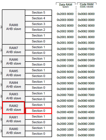
I am trying to understand the Memory layout of nRF52840 SOC in order to apply RAM retention into specific section. Looking the memory layout at pg 21 of the datasheet I can see 9 x ARM AHB slaves with total of 22 sections.
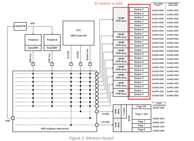
Then on pages 79-80 is the RAM[n].POWERSET register. In order to retain a memory section you have to write this register. I am very confused regarding the sections. The memory layout shows 22 sections, while the RAM[n].POWERSET register has 16 sections (A-P) for the RAM sections to be retained and accessible during System ON and 16 sections (Q-f) for the RAM sections to be retained during System OFF

The sections on the memory layout do not related with the sections on the register?  For example, section 17 (R) of RAM[n].POWERSET register, to which section in memory layout does it correspond?
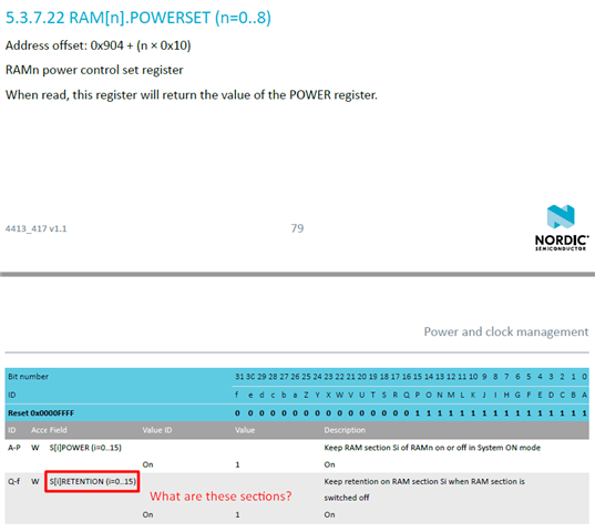
Also what is the difference between RAM[n].POWER (n=0..8) & RAM[n].POWERSET (n=0..8) registers?

Thanks in advance 

Nick

Parents Reply Children
  • Thank you for your answer Einar

    And the section (S) field within each POWER register instance represents a section within that slave

    How does it represented? For example, n=0 represents RAM0 and looking the RAM layout I see that RAM0 has two sections (Section 0 & Section 1) but the section (S) field within each POWER register instance could be 0-15 (it shouldn't be 0-1?)

    1. Section 0 & Section 1 of RAM1 which field (S[i]) within POWER register represent?

    2. Using the s140 API for RAM retention, is the snippet below correct in order to put RAM2 AHB slave section 0 in retention?

    #define RAM_AHB_slave 2
    
    ret_code_t err_code;
    err_code = sd_power_ram_power_set(RAM_AHB_slave, POWER_RAM_POWER_S2RETENTION_On << POWER_RAM_POWER_S2RETENTION_Pos);
    APP_ERROR_CHECK(err_code);

  • Hi Nick,

    Nikosant03 said:
    1. Section 0 & Section 1 of RAM1 which field (S[i]) within POWER register represent?

    This is unfortunately not clearly documented in the PS, but you can refer to the components\device\nrf52840_bitfields.h file to see this. There you can see a some relevant defines for this question:

    /* Bit 17 : Keep retention on RAM section S1 when RAM section is in OFF */
    #define POWER_RAM_POWER_S1RETENTION_Pos (17UL) /*!< Position of S1RETENTION field. */
    #define POWER_RAM_POWER_S1RETENTION_Msk (0x1UL << POWER_RAM_POWER_S1RETENTION_Pos) /*!< Bit mask of S1RETENTION field. */
    #define POWER_RAM_POWER_S1RETENTION_Off (0UL) /*!< Off */
    #define POWER_RAM_POWER_S1RETENTION_On (1UL) /*!< On */
    
    /* Bit 16 : Keep retention on RAM section S0 when RAM section is in OFF */
    #define POWER_RAM_POWER_S0RETENTION_Pos (16UL) /*!< Position of S0RETENTION field. */
    #define POWER_RAM_POWER_S0RETENTION_Msk (0x1UL << POWER_RAM_POWER_S0RETENTION_Pos) /*!< Bit mask of S0RETENTION field. */
    #define POWER_RAM_POWER_S0RETENTION_Off (0UL) /*!< Off */
    #define POWER_RAM_POWER_S0RETENTION_On (1UL) /*!< On */
    
    ...
    
    /* Bit 1 : Keep RAM section S1 ON or OFF in System ON mode. */
    #define POWER_RAM_POWER_S1POWER_Pos (1UL) /*!< Position of S1POWER field. */
    #define POWER_RAM_POWER_S1POWER_Msk (0x1UL << POWER_RAM_POWER_S1POWER_Pos) /*!< Bit mask of S1POWER field. */
    #define POWER_RAM_POWER_S1POWER_Off (0UL) /*!< Off */
    #define POWER_RAM_POWER_S1POWER_On (1UL) /*!< On */
    
    /* Bit 0 : Keep RAM section S0 ON or OFF in System ON mode. */
    #define POWER_RAM_POWER_S0POWER_Pos (0UL) /*!< Position of S0POWER field. */
    #define POWER_RAM_POWER_S0POWER_Msk (0x1UL << POWER_RAM_POWER_S0POWER_Pos) /*!< Bit mask of S0POWER field. */
    #define POWER_RAM_POWER_S0POWER_Off (0UL) /*!< Off */
    #define POWER_RAM_POWER_S0POWER_On (1UL) /*!< On */

    So for section 0, bit in position 0 controls if the section is on or off in system ON mode, and bit in position 16 controls weather it is on of off in system OFF mode. For section 1 this would be bit positions 1 and 17 respectively.

    Nikosant03 said:
    2. Using the s140 API for RAM retention, is the snippet below correct in order to put RAM2 AHB slave section 0 in retention?

    No. The AHB slave index is correct, but you are referring to section 2 in this case (which does not exist), as you use POWER_RAM_POWER_S2RETENTION_Pos (and POWER_RAM_POWER_S2RETENTION_On, though that does not really matter as it is just 1 in any case). You should have used POWER_RAM_POWER_S0RETENTION_On and POWER_RAM_POWER_S0RETENTION_Pos. Other than that it is correct.

    Br,

    Einar

  • Thank you for your effort Einar

    So for section 0, bit in position 0 controls if the section is on or off in system ON mode, and bit in position 16 controls weather it is on of off in system OFF mode. For section 1 this would be bit positions 1 and 17 respectively.

    So, If I have understood correctly for AHB slave index 0-7 there are only two sections and the assosiated bit positions are 0,1,16,17 while for AHB slave index 8 there are six sections and the assosiated bit positions are 0,1,2,3,4,5,16,17,18,19,20,21 right?

    So, actually the bits 6-15 & 22-31 of RAM[n].POWER register have no affect and I won't need them anywhere right?

Related