This post is older than 2 years and might not be relevant anymore
More Info: Consider searching for newer posts

nRF52840 Dongle Bricked After Programming

Hi,

I have a nRF52840 Dongle connected up to an external j-link debugger. I have been using this over the past few weeks with no issues and unfortunately I have managed to brick it. 

When I try to connect, i get an error saying that no board is connected. I have tried nrfproj from a comment line, the j-link lite tool and the nRFconnect programmer, all complain that they can not see the dongle.

(Actually, I had managed to do this on two separate dongles, on one the green LED remains permanently lit and on the other, there are no leds lit)

This issue seems to be similar to what Im seeing

https://devzone.nordicsemi.com/f/nordic-q-a/39596/the-nrf52840-dongle-can-no-longer-be-accessed-after-flashing-hex-file/153553#153553

Here the answers was to use the reset button. I have tried pushing, holding. tapping the reset with no changes.

How can I bring the boards back to life?

Thanks,

Rod 

Parents
  • Hi,

    This is probably due to the UCIR being deleted. The J-link lite supports only a target voltage of 3.3 V while the GPIO voltage (REG0) is by default 1.8 V on the nRF52840. The solution would be to use a debugger that is able to program down to 1.8 V volt. Other solutions are suggested in our programming dongle tutorial.

    best regards

    Jared 

  • Hi Jared,

    I have checked the tutorial again. Looking at the section 

    Recover after an accidental UICR erase

    You have two options for recovering when the REG0 (VDD) voltage is 1.8 V (typically after a UICR erase):

    • Either use a debug probe that adapts the logic levels to the target device (for instance a J-Link PRO). Program firmware that configures REGOUT0 for 3 V.
    • Or modify the dongle so that it can be supplied by an external supply and use the nRF52840 DK to program it.
      1. Adapt the dongle hardware as described under External regulated source in the nRF52840 Dongle documentation.
      2. Connect VDD from the nRF52840 DK to VDD OUT on the nRF52840 Dongle.

    I am using a j-link plus.

    I have modified my board so I am powering it from a 3.3V supply to VDDOUT.

    I still am unable to connect to the board

    Rod

Reply
  • Hi Jared,

    I have checked the tutorial again. Looking at the section 

    Recover after an accidental UICR erase

    You have two options for recovering when the REG0 (VDD) voltage is 1.8 V (typically after a UICR erase):

    • Either use a debug probe that adapts the logic levels to the target device (for instance a J-Link PRO). Program firmware that configures REGOUT0 for 3 V.
    • Or modify the dongle so that it can be supplied by an external supply and use the nRF52840 DK to program it.
      1. Adapt the dongle hardware as described under External regulated source in the nRF52840 Dongle documentation.
      2. Connect VDD from the nRF52840 DK to VDD OUT on the nRF52840 Dongle.

    I am using a j-link plus.

    I have modified my board so I am powering it from a 3.3V supply to VDDOUT.

    I still am unable to connect to the board

    Rod

Children
  • Hi,

    What voltages are you seeing on the DEC pins? Could you do an attempt to do a recover with nrfjprog -f NRF52 --recover --log and share the log? 

    regards

    Jared

  • Sorry Jared, what are the DEC pins?

    Log file below,

    Rod

  • Hi,

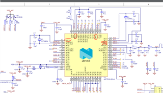
    Thanks for the log. The DEC pins as marked in the schematic below:

  • Thanks, sorry, I was looking at the pins around the board itself.

    DEC1 - 0.8V

    DEC2 - 1.2V 

    DEC3 - 3.3V

    DEC4 - 1.2V 

    DEC6 - 1.2V


  • Thank you. The DEC pins are ok. I'm suspecting that the RESET pin is held low. What voltage do you see over C27?