
Hello! I would like to use a predefined example from the nRF SDK and instead of the board's button, to use an external stimulus (let's say, an external button). Similarly, instead of turning on the board's LED, I want to set high a GPIO (let's say, external LED).
Now, I read a lot of questions on devzone about this and it's either very complicated or quite trivial. My idea is to just change in the file pca10056.h the line #define LED_1 NRF_GPIO_PIN_MAP (0,13) to #define LED_1 NRF_GPIO_PIN_MAP (0, xx). And similar for the BUTTON_1. My questions are:
1. Is this the only place where I need to do the modifications? It seems like only a mapping problem to me, but I think I might to re-write other files as well.
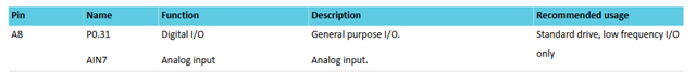
2. What do the (xx) need to be? (I read about this mapping in nRF52840's specs, @pag. 525, but I am not sure how to interpret that table into actual code). For instance, let's say that I'd like my A8 pin as a digital output (i.e. drive an external LED). Then, do I need to #define LED_1 NRF_GPIO_PIN_MAP (0, 32)? Or is A8 used already as AIN7, which is actually an analog input (see second line)?
I am a bit confused after reading a lot about this; sorry for the basic question.


