This post is older than 2 years and might not be relevant anymore
More Info: Consider searching for newer posts

SPI Reconfiguring For Bi-directional Communication

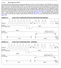
Quick question I think. I'm using the NRF52 to program a PIC16 over SPI. The PIC16 switches it's line to output once it receives a particular command so as such I need to switch the MOSI/MISO line and then back once the data is read. My understanding is the SPI must be disabled when doing this. Does this look correct?

(CLK is configured as output so will drive low when SPI is disabled)

static void configureAsOutput (void) {

  NRF_SPIM0->ENABLE = SPIM_ENABLE_ENABLE_Disabled << SPIM_ENABLE_ENABLE_Pos;
  NRF_GPIO->PIN_CNF[CFG_PIN_GLUE_DAT] = pinDisconnectInputBuffer | (GPIO_PIN_CNF_DIR_Output << GPIO_PIN_CNF_DIR_Pos);
  NRF_SPIM0->PSEL.MOSI = CFG_PIN_GLUE_DAT;
  NRF_SPIM0->PSEL.MISO = SPI_PSEL_MOSI_CONNECT_Disconnected << SPI_PSEL_MOSI_CONNECT_Pos;
  NRF_SPIM0->ENABLE = SPIM_ENABLE_ENABLE_Enabled << SPIM_ENABLE_ENABLE_Pos;
}

static uint16_t fetch (void) {

  command(0xFE); // read nvm
  NRF_SPIM0->ENABLE = SPIM_ENABLE_ENABLE_Disabled << SPIM_ENABLE_ENABLE_Pos;
  NRF_GPIO->PIN_CNF[CFG_PIN_GLUE_DAT] = (GPIO_PIN_CNF_DIR_Input << GPIO_PIN_CNF_DIR_Pos);
  NRF_SPIM0->PSEL.MOSI = SPI_PSEL_MOSI_CONNECT_Disconnected << SPI_PSEL_MOSI_CONNECT_Pos;
  NRF_SPIM0->PSEL.MISO = CFG_PIN_GLUE_DAT;
  NRF_SPIM0->ENABLE = SPIM_ENABLE_ENABLE_Enabled << SPIM_ENABLE_ENABLE_Pos;
  send(3);
  configureAsOutput();
  return rxBuffer[0] << 15 | rxBuffer[1] << 7 | rxBuffer[2] >> 1;
}

  • Hi.

    My understanding is the SPI must be disabled when doing this. Does this look correct?

    Yes, that is correct. You also need to consider the timing and use serial resistors to limit the current as you risk (or probably will) have periods of time where both devices are configured as outputs, one in a high state and the other in a low state.

  • Many thanks.

    From what I can see from the PIC programming datasheet it will only switch the line on the first CLK after the command, so I should be fine without the current limiting resistors.


    Basically I had it programming a PIC16F153xx series chip but after switching to PIC16F188xx it stopped working, despite the programming specifications being identical. There is a thread at -

    www.microchip.com/.../m1147353-p4.aspx

    So far:

    1. NRF52 looks like it's sending DAT & CLK fine (on scope).
    2. Pins correct and tested
    3. PIC held at same Vdd as NRF (Schmidt mode by default).

    I'll publish this library on github once I get the verification side of it working. The NRF52 and a PIC16 as a glue chip & 5v driver is quite the powerful combination!

    If you have a few minutes and can spot anything obvious on that thread it would be much appreciated as I seem to have exhausted everyone's ideas.

    Regards,

    Andrew

Related