Hi,
We are looking for a guideline to trigger GPIO and SAADC sampling at the same time.
Our purpose is to sample every 20 m
Hi,
We are looking for a guideline to trigger GPIO and SAADC sampling at the same time.
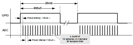
Our purpose is to sample every 20 ms - 5 ADC channels, 16 samples for each channel, at total 80 samples – sample rate of 25us.
Upon enabling PPI we need to set a GPIO and when finish sampling clear the GPIO.
For now, we are using NRF_DRV_TIMER, setting the timer channel in extended compare mode, configured to 20 ms. In the Event handler of the timer, we configure SAADC write buffer, enable the PPI channel and setting the GPIO.
Upon getting the SAADC callback we disable PPI channel and clearing the GPIO, and wait for timer event and so on.
Using this implementation we have latency between the ADC sampling and the GPIO, therefore we are looking for a proper way to sync between these 2 tasks.
The picture below shows the required timing:
s - 5 ADC channels, 16 samples for each channel, at total 80 samples – sample rate of 25us.
Upon enabling PPI we need to set a GPIO and when finish sampling clear the GPIO.
For now, we are using NRF_DRV_TIMER, setting the timer channel in extended compare mode, configured to 20 ms. In the Event handler of the timer, we configure SAADC write buffer, enable the PPI channel and setting the GPIO.
Upon getting the SAADC callback we disable PPI channel and clearing the GPIO, and wait for timer event and so on.
Using this implementation we have latency between the ADC sampling and the GPIO, therefore we are looking for a proper way to sync between these 2 tasks.
The picture attached shows the required timing
Thanks,
Ran