This post is older than 2 years and might not be relevant anymore
More Info: Consider searching for newer posts

SPIM #3 MOSI must be tied to ground via capacitor to work

Hi,

I am using an Adafruit nrf52840 Feather board and have been having a problem with SPIM instance # 3.

I have the board connected to a display module and have been successful in using SPI #0-2, and SPIM instances 0-2, without changing the hardware and just switching the config and building.

When I use SPI(#0-2) I can successfully initialize the display, with no change of hardware or pins.

When I switch to use SPIM(#0-2) I can successfully initialize the display, with no change of hardware or pins.

As soon as I configure to use SPIM #3, with no change of hardware or pins, it fails to initialize the display!

I started research and use my oscilloscope to see what was happening on the MOSI pin and as soon as I attached the probe it started to work....I removed the probe and it stopped working again.  I then wondered if it could be capacitance, so I connected a 15pF capacitor from MOSI -> ground and it began to work.

I had the speed set at 10Mhz and so I dropped it to 250khz in case was a speed problem, and it still needs the capacitor when using SPIM #3.

Does anyone have a clue what it going on?

Any help is appreciated.

Thanks

Mark


Parents
  • That is very strange, usually the failure mode is too much capacitance on an SPI bus. 

    Try setting high driver strength on the GPIOs for SCK, MOSI, and MISO, prior to initializing the SPI driver.

  • Hi,

    I set the SCK and MOSI lines to high drive (not using the MISO line) and made no difference.

    I thought I would try to take a look at the waveform with and without the capacitor and see what effect it had, but when I connect the oscilloscope probe to the MISO line it works again, so that does not help me.

    What I find strange, as I said in the orig post, is that all works well, even at max 8Mhz when using SPI and SPIM#0-2, but as soon as I configure of SPIM#3 the capacitor is needed, even at lower speeds.

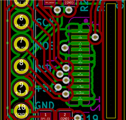
    Is there any kind of testing I can do without power to the device....basic checks on the wiring?  I looked at my custom board I use to interface to the display and nothing jumps out at me.  The SPI and MOSI lines go direct to the display and cross over the reset line on the ground plane. Image of board is attached.

      Any help diagnosing the problem is appreciated.

  • If using a write-only SPI display then it is not clear why there is even a MISO pin; perhaps try not defining what is probably a floating pin in this design, as un-terminated pins defined as SPI MISO can generate all types of nuisance when assorted clocks are bashing about on nearby pins, and the capacitor is simply reducing that interference. If using Nordic drivers change the pin to disconnected thus:

    #define NRFX_SPIM_MISO_PIN    NRFX_SPIM_PIN_NOT_USED // not used

    if using direct hardware control instead use

    PSEL.MISO = 0x80000000;  / low-level pin disconnected
    ie same as
    PSEL.MISO = SPIS_PSEL_MISO_CONNECT_Msk;
    or
    PSEL.MISO = NRF_SPIM_PIN_NOT_CONNECTED; // 0xFFFFFFFF
    
    These all set the MS-Bit (bit 31) to '1'

    Be careful not to mix these; NRFX_SPIM_PIN_NOT_USED is defined differently - 0xFF, which only works with the driver not the pin control register.

  • Sorry guys I have been getting confused when writing this between my MISO and MOSI.....the problem is with the MOSI pin needing a capacitor....the MISO pin is not connected/not used.  I will check my sdk_config settings to make sure I have correctly disabled the MISO pin.

Reply Children
  • Given that you needed to add capacitance you might have an issue with ringing due to a highly inductive load, or other kinds of EMI.

    Are you using particularly long leads or something? 

    Do you use the same GPIOs for SPIM3 as SPIM0-2? 

    Do you see the same problem on the nRF52840 DK?

    I suggest you ask on the adafruit forums as well. There might be known issues with their layout with regards to GPIOs.

  • Hi,

    I am using hook up wires on my breadboard, so they are approx 2" long.

    I am using the same GPIO for SPIM3 as when I use SPI and SPIM0-2...I just change the config and rebuild and no longer works without capacitor on SPIM3.

    Makes me think there is something diff inside the nrf52840 chip that allows SPIM3 to handle the higher clock speeds (16/32 Mhz), but at the same time also means I need a capacitor, especially when I am making no changes to the hardware each time I switch SPI's.

    What I have not done is test SPIM3 with 16/32 Mhz clock speed yet.  Will do that next...especially as that is why I wanted to use SPIM3.

    Good idea for me to post something on Adafruit forums too.

    Thanks for the response.

  • winneymj said:
    What I have not done is test SPIM3 with 16/32 Mhz clock speed yet.  Will do that next...especially as that is why I wanted to use SPIM3.

     Also test at lower speeds. 

    And can you share an analog scope of the SPIM3 vs SPIM0-2 at 8MHz?

  • Hi,

    I went down to 250 khz and still needed capacitor for SPIM3, but not for other SPI's.

    Will see what I can capture from the scope.  Only problem is that when I connect my scope to MOSI it adds the capacitance back and the SPIM3 works.  Worth a try though.  Will try grabbing that tonight.

    Thanks 

  • If you don't have high drive correctly set for both SCK and MOSI then you will not get reliable operation on SPI3; ideally this should be verified by setting a breakpoint and looking at the PO configuration just before or just after a transfer. Note the following is not going to work:

    "Try setting high driver strength on the GPIOs for SCK, MOSI, and MISO, prior to initializing the SPI driver."

    You have to set high drive for SCK and MOSI after doing the init as the init sets low drive on the pins.

Related