This post is older than 2 years and might not be relevant anymore
More Info: Consider searching for newer posts

1uS serial waveform construction at 3.3V

Hello!

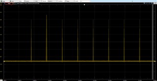
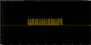
I am trying to interface with some old hardware that communicates over a single data pin. I need to take in varying 32-bit packets and output the data that translates each bit into a specific 1uS-base waveform. E.g. 0 = 3uS Low + 1uS High ; 1 = 1uS Low + 3uS High. This is needs to be at 3.3V logic. 

My question is on approach to this (assuming this is possible), I'm not totally experienced in using the hardware peripherals for the latest nRF52 chips but I do have a few 840 DKs to test with. Should I go about this using PWM? Or should I construct this solution using GPIOTE and PPI timers? Some other peripheral that would work well here?

I'm poking around the pwm and gpiote examples in SDK 16 as I come up with a solution but thought I'd post here to see if there was as better way than what I come up with. 

Many thanks in advance!

Sam

Parents
  • Hi Sam,

    I think the most simple way is to use SPIM peripheral (you need only MOSI output). For example, at 1 Mbps you can encode two bits in one byte: 4'b0001 for zero and 4'b0111 for one. You can also use PWM, but it would require more complex configuration and will consume more power at high frequencies.

  • Thanks Dmitry! Would you be able to point me to any posts that deal with constructing a 1Mbps waveform with SPI? I am quite inexperienced with the inner workings of SPI moreover, but I'm starting with the examples/peripheral/spi from the SDK. How might I build from this example? I can see how data is transferred but unsure how I would get a nice waveform that I can read on a scope. (Right now the MOSI pin readout from the spi example isn't making any sense to me at all) 

Reply
  • Thanks Dmitry! Would you be able to point me to any posts that deal with constructing a 1Mbps waveform with SPI? I am quite inexperienced with the inner workings of SPI moreover, but I'm starting with the examples/peripheral/spi from the SDK. How might I build from this example? I can see how data is transferred but unsure how I would get a nice waveform that I can read on a scope. (Right now the MOSI pin readout from the spi example isn't making any sense to me at all) 

Children
  • What's wrong with waveform? You should see an exact sequence of bits encoded in m_tx_buf. For example, { 0x11,0x77 } should make up two zeroes (00010001) then two ones (01110111).

  • I placed different values in m_tx_buf but still get these same little ticks across the MOSI pin (29) no matter the value. At first I thought I had a setting wrong in the scope software but I observed the pwm examples with correct waveforms showing up as they would normally. Am I doing something wrong here?

    #include "nrf_drv_spi.h"
    #include "app_util_platform.h"
    #include "nrf_gpio.h"
    #include "nrf_delay.h"
    #include "boards.h"
    #include "app_error.h"
    #include <string.h>
    #include "nrf_log.h"
    #include "nrf_log_ctrl.h"
    #include "nrf_log_default_backends.h"
    
    #define SPI_INSTANCE  0 /**< SPI instance index. */
    static const nrf_drv_spi_t spi = NRF_DRV_SPI_INSTANCE(SPI_INSTANCE);  /**< SPI instance. */
    static volatile bool spi_xfer_done;  /**< Flag used to indicate that SPI instance completed the transfer. */
    
    #define TEST_STRING0 0x11
    #define TEST_STRING1 0x77
    static uint8_t       m_tx_buf[] = {TEST_STRING0};         /**< TX buffer. */
    static uint8_t       m_rx_buf[sizeof(m_tx_buf) + 1];     /**< RX buffer. */
    static const uint8_t m_length = sizeof(m_tx_buf);        /**< Transfer length. */
    
    /**
     * @brief SPI user event handler.
     * @param event
     */
    void spi_event_handler(nrf_drv_spi_evt_t const * p_event,
                           void *                    p_context)
    {
        spi_xfer_done = true;
        NRF_LOG_INFO("Transfer completed.");
        if (m_rx_buf[0] != 0)
        {
            NRF_LOG_INFO(" Received:");
            NRF_LOG_HEXDUMP_INFO(m_rx_buf, strlen((const char *)m_rx_buf));
        }
    }
    
    int main(void)
    {
        bsp_board_init(BSP_INIT_LEDS);
    
        APP_ERROR_CHECK(NRF_LOG_INIT(NULL));
        NRF_LOG_DEFAULT_BACKENDS_INIT();
    
        nrf_drv_spi_config_t spi_config = NRF_DRV_SPI_DEFAULT_CONFIG;
        spi_config.ss_pin   = SPI_SS_PIN;
        spi_config.miso_pin = SPI_MISO_PIN;
        spi_config.mosi_pin = SPI_MOSI_PIN;
        spi_config.sck_pin  = SPI_SCK_PIN;
        APP_ERROR_CHECK(nrf_drv_spi_init(&spi, &spi_config, spi_event_handler, NULL));
    
        NRF_LOG_INFO("SPI example started.");
    
        while (1)
        {
            // Reset rx buffer and transfer done flag
            memset(m_rx_buf, 0, m_length);
            spi_xfer_done = false;
    
            APP_ERROR_CHECK(nrf_drv_spi_transfer(&spi, m_tx_buf, m_length, m_rx_buf, m_length));
    
            while (!spi_xfer_done)
            {
                __WFE();
            }
    
            NRF_LOG_FLUSH();
    
            bsp_board_led_invert(BSP_BOARD_LED_0);
            nrf_delay_ms(200);
        }
    }

  • You're watching your signal at 4kHz sampling rate, to see 1Mbps signal, you need at least 2MHz sampling rate. Also, NRF_DRV_SPI_DEFAULT_CONFIG has 4Mbps default settings, you need to set spi_config.frequency = NRF_DRV_SPI_FREQ_1M for 1Mbps.

  • Hey good catch Dmitry. After adjusting the sample rate I can start to see some recognizable pulses, and I've managed to construct an appropriate waveform, however the data are still far apart from each other, what do I need to change in order to control the delay after my data has been transferred?

  • Hi Sam,

    did you have success with your waveform?

Related