This post is older than 2 years and might not be relevant anymore
More Info: Consider searching for newer posts

[nRF52840] Poor RF Performance on Custom PCB with Chip Antenna

Hi,

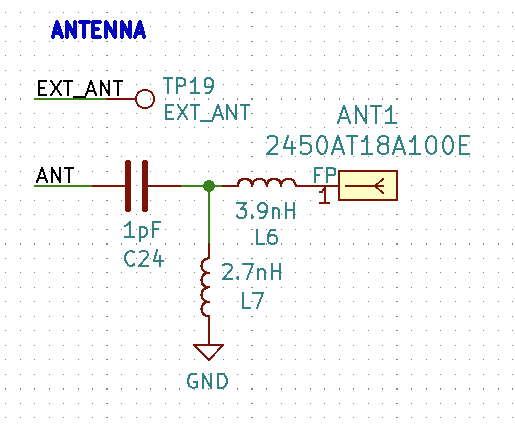
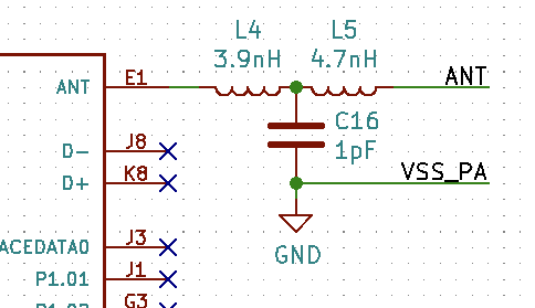
I have a custom PCB using the Johanson 2450AT18A100E chip antenna. For some reason, I'm getting extremely subpar RF performance and so I'm taking a second look at my RF path. Is my signal path out of the ANT pin of the nRF52840-CKAA through to the feed line of the chip antenna is correct? I am using the reference design for the nRF52840 CKAA and then feeding the output of the into the matching network from the Johanson datasheet.

Thanks
Parents Reply
  • Hey ketiljo,


    Thanks for the tips. When you say C1 and C7, you're referring to C16 and L7 on my schematic, correct? 

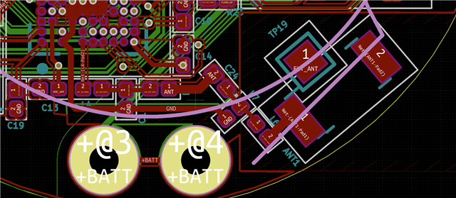
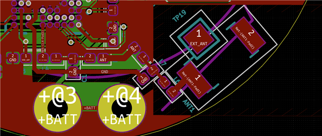
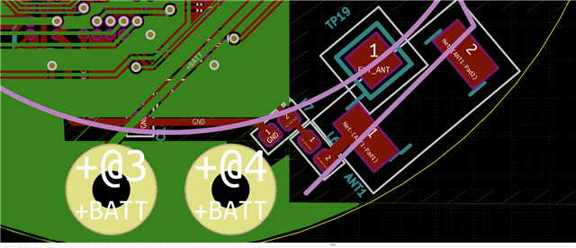
    TP19 was placed down so that the chip antenna could be reworked with a UFL connector for test and debug purposes. Plan on removing this for future iterations. 

    The bottom side is actually a 1v8 power plane instead of a ground plane... Do you think this is what's causing the lackluster performance?

Children
  • Yes, C16 and L7, sorry.

    It's preferable to have a ground plane instead of a power plane. From a AC point of view, they are the same, but you can't connect the power plane to the ground plane the same way you could do with an inner ground plane. It's important to use plenty of vias to connect the different ground planes together for a low impedance ground connection. 

Related