Hi,
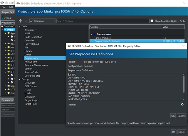
in my project I have a custom board with a nRF52832 chip that reads SAADC data and transmits this data (peripheral role). This data is received by a nRF52840-DK board (central role) and written into a COM-Port of a pc. I flashed the "ble_app_uart_c" example into the nRF52840-DK and the "ble_app_uart__saadc_timer_driven__scan_mode" example into the custom board with the nRF52832 chip (nRF5_SDK_17.0.0_9d13099). This configuration works fine. The SAADC data gets transmitted by the nRF52832 custom board, received by the nRF52840-DK and written into the COM-Port of my PC.
My problem is the SAADC sampling rate (SAADC_SAMPLE_RATE) of the "ble_app_uart__saadc_timer_driven__scan_mode" example. By default the SAADC sampling rate is 250ms (4Hz). I need to increase this sampling rate to 1ms (1000Hz). But if I choose the SAADC_SAMPLE_RATE < 10ms (>100Hz) an error occured and the chip resets and tries to reconnect. I receive the following error code if I debug the ble_app_uart__saadc_timer_driven__scan_mode example:
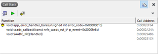
which is produced by the ble_nus_data_send(...) function in main.c:
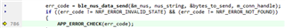
Unfortunaly, I am not able to find a error description for this error code.
Can you please tell me, how to increase the sampling rate of the "ble_app_uart__saadc_timer_driven__scan_mode" example to 1ms (=1000Hz)?