
Hello,
I uses the NORDIC project saadc_low_power. A counter was built into this so that only a defined number of samples are carried out.
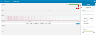
Measuring current on an nRF5 DK while debugging.
Here are the code extensions
#define MAX_SAADC_SAMPLE_CNT ( 1000 )
static uint32_t saadc_sample_cnt = 0;
if( saadc_sample_cnt < MAX_SAADC_SAMPLE_CNT )
{
saadc_sample_cnt++;
nrf_drv_saadc_sample(); //Trigger the SAADC SAMPLE task
….
Both variants work with the debugger.
If max Sample 1000, the measurement works - see file saadc_low_power_counter_1000_okay.png
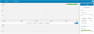
If max Sample 100, the measurement does not work - see:
- saadc_low_power_counter_100_not_okay.png
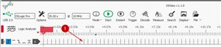
- saadc_low_power_counter_100_with debugger_okay.png
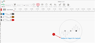
- saadc_low_power_counter_100_with PPK_not_okay.png
Why is the test not working at 100. This can also be seen on the GPIO port.
Many thanks in advance
Many greetings
/**
 * Copyright (c) 2014 - 2017, Nordic Semiconductor ASA
 *
 * All rights reserved.
 *
 * Redistribution and use in source and binary forms, with or without modification,
 * are permitted provided that the following conditions are met:
 *
 * 1. Redistributions of source code must retain the above copyright notice, this
 *    list of conditions and the following disclaimer.
 *
 * 2. Redistributions in binary form, except as embedded into a Nordic
 *    Semiconductor ASA integrated circuit in a product or a software update for
 *    such product, must reproduce the above copyright notice, this list of
 *    conditions and the following disclaimer in the documentation and/or other
 *    materials provided with the distribution.
 *
 * 3. Neither the name of Nordic Semiconductor ASA nor the names of its
 *    contributors may be used to endorse or promote products derived from this
 *    software without specific prior written permission.
 *
 * 4. This software, with or without modification, must only be used with a
 *    Nordic Semiconductor ASA integrated circuit.
 *
 * 5. Any software provided in binary form under this license must not be reverse
 *    engineered, decompiled, modified and/or disassembled.
 *
 * THIS SOFTWARE IS PROVIDED BY NORDIC SEMICONDUCTOR ASA "AS IS" AND ANY EXPRESS
 * OR IMPLIED WARRANTIES, INCLUDING, BUT NOT LIMITED TO, THE IMPLIED WARRANTIES
 * OF MERCHANTABILITY, NONINFRINGEMENT, AND FITNESS FOR A PARTICULAR PURPOSE ARE
 * DISCLAIMED. IN NO EVENT SHALL NORDIC SEMICONDUCTOR ASA OR CONTRIBUTORS BE
 * LIABLE FOR ANY DIRECT, INDIRECT, INCIDENTAL, SPECIAL, EXEMPLARY, OR
 * CONSEQUENTIAL DAMAGES (INCLUDING, BUT NOT LIMITED TO, PROCUREMENT OF SUBSTITUTE
 * GOODS OR SERVICES; LOSS OF USE, DATA, OR PROFITS; OR BUSINESS INTERRUPTION)
 * HOWEVER CAUSED AND ON ANY THEORY OF LIABILITY, WHETHER IN CONTRACT, STRICT
 * LIABILITY, OR TORT (INCLUDING NEGLIGENCE OR OTHERWISE) ARISING IN ANY WAY OUT
 * OF THE USE OF THIS SOFTWARE, EVEN IF ADVISED OF THE POSSIBILITY OF SUCH DAMAGE.
 *
 */
/**
 * Perhipheral: nRF52 SAADC
 * Compatibility: nRF52832 rev 1/nRF52840 Eng A, nRF5 SDK 13.0.0
 * Softdevice used: No softdevice
 *

 * This example enables the RTC timer to periodically trigger SAADC sampling. RTC is chosen here instead of
 * TIMER because it is low power. The example samples on a single input pin, the AIN0, which maps to physical pin P0.02 on the nRF52832 IC.
 * This SAADC example shows the following features:
 * - Low Power -> Enabled with initializing SAADC when sampling and uninitializing when sampling is complete.
 *                Low power can only be obtained when UART_PRINTING_ENABLED is not defined and
 *                SAADC_SAMPLES_IN_BUFFER is 1
 * - Oversampling -> This reduces SAADC noise level, especially for higher SAADC resolutions, see
 *                   https://devzone.nordicsemi.com/question/83938/nrf52832-saadc-sampling/?comment=84340#comment-84340
 *                   Configured with the SAADC_OVERSAMPLE constant.
 * - BURST mode -> Burst mode can be combined with oversampling, which makes the SAADC sample all oversamples as fast
 *                 as it can with one SAMPLE task trigger. Set the SAADC_BURST_MODE constant to enable BURST mode.
 * - Offset Calibration -> SAADC needs to be occasionally calibrated. The desired calibration interval depends on the
 *                         expected temperature change rate, see the nRF52832 PS for more information. The
 *                         calibration interval can be adjusted with configuring the SAADC_CALIBRATION_INTERVAL
 *                         constant.
 * The SAADC sample result is printed on UART. To see the UART output, a UART terminal (e.g. Realterm) can be configured on
 * your PC with the UART configuration set in the uart_config function, which is also described in the saadc example documentation ->
 * http://infocenter.nordicsemi.com/topic/com.nordic.infocenter.sdk5.v11.0.0/nrf_dev_saadc_example.html?cp=5_0_0_4_5_24
 *

 * Indicators on the nRF52-DK board:
 * LED1: SAADC Sampling triggered
 * LED2: SAADC sampling buffer full and event received
 * LED3: SAADC Offset calibration complete
 */

#include <stdbool.h>
#include <stdint.h>
#include <stdio.h>
#include <string.h>
#include "nrf.h"
#include "nrf_drv_saadc.h"
#include "boards.h"
#include "app_error.h"
#include "app_util_platform.h"
#include "nrf_pwr_mgmt.h"
#include "nrf_drv_power.h"
#include "nrf_drv_clock.h"
#include "nrf_drv_rtc.h"

#include "nrf_log.h"
#include "nrf_log_ctrl.h"
#include "nrf_log_default_backends.h"

#define RTC_FREQUENCY 32                          //Determines the RTC frequency and prescaler
#define RTC_CC_VALUE 8                            //Determines the RTC interrupt frequency and thereby the SAADC sampling frequency
#define SAADC_SAMPLE_INTERVAL_MS 250              //Interval in milliseconds at which RTC times out and triggers SAADC sample task (
#define SAADC_CALIBRATION_INTERVAL 5              //Determines how often the SAADC should be calibrated relative to NRF_DRV_SAADC_EVT_DONE event. E.g. value 5 will make the SAADC calibrate every fifth time the NRF_DRV_SAADC_EVT_DONE is received.
#define SAADC_SAMPLES_IN_BUFFER 1                 //Number of SAADC samples in RAM before returning a SAADC event. For low power SAADC set this constant to 1. Otherwise the EasyDMA will be enabled for an extended time which consumes high current.
#define SAADC_OVERSAMPLE NRF_SAADC_OVERSAMPLE_DISABLED  //Oversampling setting for the SAADC. Setting oversample to 4x This will make the SAADC output a single averaged value when the SAMPLE task is triggered 4 times. Enable BURST mode to make the SAADC sample 4 times when triggering SAMPLE task once.
#define SAADC_BURST_MODE 0                        //Set to 1 to enable BURST mode, otherwise set to 0.

#define MAX_SAADC_SAMPLE_CNT ( 100 )
// #define MAX_SAADC_SAMPLE_CNT ( 0xFFFFFFFF)
#define GPIO_PIN_MEASURE_1  24  // DIO zur Zeitmessung

const  nrf_drv_rtc_t           rtc = NRF_DRV_RTC_INSTANCE(2); /**< Declaring an instance of nrf_drv_rtc for RTC2. */
static uint32_t                rtc_ticks = RTC_US_TO_TICKS(SAADC_SAMPLE_INTERVAL_MS*1000, RTC_FREQUENCY);
static nrf_saadc_value_t       m_buffer_pool[2][SAADC_SAMPLES_IN_BUFFER];
static uint32_t                m_adc_evt_counter = 0;
static bool                    m_saadc_calibrate = false;


static uint32_t saadc_sample_cnt = 0;


static void rtc_handler(nrf_drv_rtc_int_type_t int_type)
{
    uint32_t err_code;

    if (int_type == NRF_DRV_RTC_INT_COMPARE0)
    {
        if( saadc_sample_cnt < MAX_SAADC_SAMPLE_CNT)
        {
            saadc_sample_cnt++;

            nrf_gpio_pin_write( GPIO_PIN_MEASURE_1, 1);

            nrf_drv_saadc_sample();                                        //Trigger the SAADC SAMPLE task

            LEDS_INVERT(BSP_LED_0_MASK);                                   //Toggle LED1 to indicate SAADC sampling start

            err_code = nrf_drv_rtc_cc_set(&rtc, 0, rtc_ticks, true);       //Set RTC compare value. This needs to be done every time as the nrf_drv_rtc clears the compare register on every compare match
            APP_ERROR_CHECK(err_code);
            nrf_drv_rtc_counter_clear(&rtc);                               //Clear the RTC counter to start count from zero


            nrf_gpio_pin_write( GPIO_PIN_MEASURE_1, 0);
        }
    }
}

static void lfclk_config(void)
{
    ret_code_t err_code = nrf_drv_clock_init();                        //Initialize the clock source specified in the nrf_drv_config.h file, i.e. the CLOCK_CONFIG_LF_SRC constant
    APP_ERROR_CHECK(err_code);
    nrf_drv_clock_lfclk_request(NULL);
}

static void rtc_config(void)
{

    uint32_t err_code;

    //Initialize RTC instance
    nrf_drv_rtc_config_t rtc_config;
    rtc_config.prescaler = RTC_FREQ_TO_PRESCALER(RTC_FREQUENCY);
    err_code = nrf_drv_rtc_init(&rtc, &rtc_config, rtc_handler);                //Initialize the RTC with callback function rtc_handler. The rtc_handler must be implemented in this applicaiton. Passing NULL here for RTC configuration means that configuration will be taken from the sdk_config.h file.
    APP_ERROR_CHECK(err_code);

    err_code = nrf_drv_rtc_cc_set(&rtc, 0, rtc_ticks, true);                    //Set RTC compare value to trigger interrupt. Configure the interrupt frequency by adjust RTC_CC_VALUE and RTC_FREQUENCY constant in top of main.c
    APP_ERROR_CHECK(err_code);

    //Power on RTC instance
    nrf_drv_rtc_enable(&rtc);                                                   //Enable RTC
}


void saadc_callback(nrf_drv_saadc_evt_t const * p_event)
{
    ret_code_t err_code;
    if (p_event->type == NRF_DRV_SAADC_EVT_DONE)                                //Capture offset calibration complete event
    {

        LEDS_INVERT(BSP_LED_1_MASK);                                            //Toggle LED2 to indicate SAADC buffer full

        if((m_adc_evt_counter % SAADC_CALIBRATION_INTERVAL) == 0)               //Evaluate if offset calibration should be performed. Configure the SAADC_CALIBRATION_INTERVAL constant to change the calibration frequency
        {
            m_saadc_calibrate = true;                                           // Set flag to trigger calibration in main context when SAADC is stopped
        }

        NRF_LOG_INFO("ADC event number: %d",(int)m_adc_evt_counter);        //Print the event number on UART

        for (int i = 0; i < p_event->data.done.size; i++)
        {
            NRF_LOG_INFO("%d", p_event->data.done.p_buffer[i]);             //Print the SAADC result on UART
        }

        if(m_saadc_calibrate == false)
        {
            err_code = nrf_drv_saadc_buffer_convert(p_event->data.done.p_buffer, SAADC_SAMPLES_IN_BUFFER);             //Set buffer so the SAADC can write to it again.
            APP_ERROR_CHECK(err_code);
        }

        m_adc_evt_counter++;

    }
    else if (p_event->type == NRF_DRV_SAADC_EVT_CALIBRATEDONE)
    {
        LEDS_INVERT(BSP_LED_2_MASK);                                                                    //Toggle LED3 to indicate SAADC calibration complete

        err_code = nrf_drv_saadc_buffer_convert(m_buffer_pool[0], SAADC_SAMPLES_IN_BUFFER);             //Set buffer so the SAADC can write to it again.
        APP_ERROR_CHECK(err_code);
        err_code = nrf_drv_saadc_buffer_convert(m_buffer_pool[1], SAADC_SAMPLES_IN_BUFFER);             //Need to setup both buffers, as they were both removed with the call to nrf_drv_saadc_abort before calibration.
        APP_ERROR_CHECK(err_code);

        NRF_LOG_INFO("SAADC calibration complete !");                                              //Print on UART
    }
}


void saadc_init(void)
{
    ret_code_t err_code;
    nrf_drv_saadc_config_t saadc_config;
    nrf_saadc_channel_config_t channel_config;


    //Configure SAADC
    saadc_config.low_power_mode = true;                                                   //Enable low power mode.
    saadc_config.resolution = NRF_SAADC_RESOLUTION_12BIT;                                 //Set SAADC resolution to 12-bit. This will make the SAADC output values from 0 (when input voltage is 0V) to 2^12=4096 (when input voltage is 3.6V for channel gain setting of 1/6).
    saadc_config.oversample = SAADC_OVERSAMPLE;                                           //Set oversample to 4x. This will make the SAADC output a single averaged value when the SAMPLE task is triggered 4 times.
    saadc_config.interrupt_priority = APP_IRQ_PRIORITY_LOW;                               //Set SAADC interrupt to low priority.

    //Initialize SAADC
    err_code = nrf_drv_saadc_init(&saadc_config, saadc_callback);                         //Initialize the SAADC with configuration and callback function. The application must then implement the saadc_callback function, which will be called when SAADC interrupt is triggered
    APP_ERROR_CHECK(err_code);

    //Configure SAADC channel
    channel_config.reference = NRF_SAADC_REFERENCE_INTERNAL;                              //Set internal reference of fixed 0.6 volts
    channel_config.gain = NRF_SAADC_GAIN1_6;                                              //Set input gain to 1/6. The maximum SAADC input voltage is then 0.6V/(1/6)=3.6V. The single ended input range is then 0V-3.6V
    channel_config.acq_time = NRF_SAADC_ACQTIME_10US;                                     //Set acquisition time. Set low acquisition time to enable maximum sampling frequency of 200kHz. Set high acquisition time to allow maximum source resistance up to 800 kohm, see the SAADC electrical specification in the PS.
    channel_config.mode = NRF_SAADC_MODE_SINGLE_ENDED;                                    //Set SAADC as single ended. This means it will only have the positive pin as input, and the negative pin is shorted to ground (0V) internally.
    if(SAADC_BURST_MODE)
    {
        channel_config.burst = NRF_SAADC_BURST_ENABLED;                                   //Configure burst mode for channel 0. Burst is useful together with oversampling. When triggering the SAMPLE task in burst mode, the SAADC will sample "Oversample" number of times as fast as it can and then output a single averaged value to the RAM buffer. If burst mode is not enabled, the SAMPLE task needs to be triggered "Oversample" number of times to output a single averaged value to the RAM buffer.
    }
    channel_config.pin_p = NRF_SAADC_INPUT_VDD;                                           //Select the input pin for the channel. VDD pin maps to physical pin P0.02.
    // channel_config.pin_p = NRF_SAADC_INPUT_AIN0;                                          //Select the input pin for the channel. AIN0 pin maps to physical pin P0.02.
    channel_config.pin_n = NRF_SAADC_INPUT_DISABLED;                                      //Since the SAADC is single ended, the negative pin is disabled. The negative pin is shorted to ground internally.
    channel_config.resistor_p = NRF_SAADC_RESISTOR_DISABLED;                              //Disable pullup resistor on the input pin
    channel_config.resistor_n = NRF_SAADC_RESISTOR_DISABLED;                              //Disable pulldown resistor on the input pin


    //Initialize SAADC channel
    err_code = nrf_drv_saadc_channel_init(0, &channel_config);                            //Initialize SAADC channel 0 with the channel configuration
    APP_ERROR_CHECK(err_code);

    err_code = nrf_drv_saadc_buffer_convert(m_buffer_pool[0],SAADC_SAMPLES_IN_BUFFER);    //Set SAADC buffer 1. The SAADC will start to write to this buffer
    APP_ERROR_CHECK(err_code);

    err_code = nrf_drv_saadc_buffer_convert(m_buffer_pool[1],SAADC_SAMPLES_IN_BUFFER);    //Set SAADC buffer 2. The SAADC will write to this buffer when buffer 1 is full. This will give the applicaiton time to process data in buffer 1.
    APP_ERROR_CHECK(err_code);

}


/**
 * @brief Function for main application entry.
 */
int main(void)
{
    LEDS_CONFIGURE(LEDS_MASK);                       //Configure all leds
    LEDS_OFF(LEDS_MASK);                             //Turn off all leds

    NRF_POWER->DCDCEN = 1;                           //Enabling the DCDC converter for lower current consumption

    uint32_t err_code = NRF_LOG_INIT(NULL);
    APP_ERROR_CHECK(err_code);                       //Configure Logging. LOGGING is used to show the SAADC sampled result. Default is UART, but RTT can be configured in sdk_config.h
    NRF_LOG_DEFAULT_BACKENDS_INIT();
    NRF_LOG_INFO("SAADC Low Power Example.");

    lfclk_config();                                  //Configure low frequency 32kHz clock
    rtc_config();                                    //Configure RTC. The RTC will generate periodic interrupts. Requires 32kHz clock to operate.

    saadc_init();                                    //Initialize and start SAADC

    nrf_gpio_cfg_output( GPIO_PIN_MEASURE_1 );
    nrf_gpio_pin_clear( GPIO_PIN_MEASURE_1 );


    while (1)
    {
        if(m_saadc_calibrate == true)
        {
            nrf_drv_saadc_abort();                                  // Abort all ongoing conversions. Calibration cannot be run if SAADC is busy
            NRF_LOG_INFO("SAADC calibration starting...");    //Print on UART

            while(nrf_drv_saadc_calibrate_offset() != NRF_SUCCESS); //Trigger calibration task
            m_saadc_calibrate = false;
        }
        while(NRF_LOG_PROCESS() != NRF_SUCCESS);
        nrf_pwr_mgmt_run();

    }
}


/** @} */

