This post is older than 2 years and might not be relevant anymore
More Info: Consider searching for newer posts

Can mistuned crystal oscillator circuit affect Nordic RF power output?

Hello,

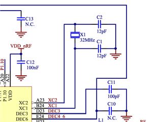
I experimented with some different capacitor tuning values at C1/C2; the external 32MHz clock initializes just fine for C1=C2=10pF, C1=C2=12pF (nominal), and C1=C2=15pF.

Will the capacitor value used for C1/C2 impact RF output power (and not just output frequency), and if so then by how much?

Thanks in advance.

Parents
  • What is the CL value of the Crystal you are using?  Have you looked at the carrier frequency to see what value load cap is the best?  To answer your question,  the load cap value will not change the power output of the device.  However it will effect the carrier frequency (Transmit and Receiver)   the 10pF and 12pF would be good values for a crystal with a CL value of 7pF ~ 8pF.  The 15pF load cap would be good for a crystal with a CL value of  10pF.

  • Hi Jay,

    Thanks for your response.  We are using the recommended value for the crystal (and also the recommended from the reference design for the nRF52840): 12pF.

    I know in the simplistic concept of a mixer, the output signal amplitude depends on both the RF input AND clock/LO input amplitude.  I guess I am asking indirectly if there is some circuit inside the nRF52840 chip (XC1 and XC2 inputs) that conditions the clock signal before it goes into the mixer, so that the RF output power level varies with the RF input power level, as opposed to both RF in and LO power levels.

    So from what you're saying, the answer is "Yes, there is an internal circuit that conditions the clock/LO signal amplitude so that RF output varies mostly with the RF input," or perhaps "No, there is not a special circuit, but the software takes care of it."

    Am I interpreting this correctly?  If you can comment as to whether or not it is hardware or software, that'd be helpful.

    Thanks again for your help!  I really appreciate it.  

    Luke

Reply
  • Hi Jay,

    Thanks for your response.  We are using the recommended value for the crystal (and also the recommended from the reference design for the nRF52840): 12pF.

    I know in the simplistic concept of a mixer, the output signal amplitude depends on both the RF input AND clock/LO input amplitude.  I guess I am asking indirectly if there is some circuit inside the nRF52840 chip (XC1 and XC2 inputs) that conditions the clock signal before it goes into the mixer, so that the RF output power level varies with the RF input power level, as opposed to both RF in and LO power levels.

    So from what you're saying, the answer is "Yes, there is an internal circuit that conditions the clock/LO signal amplitude so that RF output varies mostly with the RF input," or perhaps "No, there is not a special circuit, but the software takes care of it."

    Am I interpreting this correctly?  If you can comment as to whether or not it is hardware or software, that'd be helpful.

    Thanks again for your help!  I really appreciate it.  

    Luke

Children
  • Hi,


    The output power has no dependency on the crystal signal swing, this is just used as a frequency reference for the radio. If inaccurate, the center frequency will shift, but the output power will stay within what is otherwise the variation inside the band and between the channels: very low. 

    The crystal will start up just fine as you say, but you need to tune it(by adjusting the load caps) that the actual RF carrier is as close to the configured frequency. The requirement for Bluetooth compliance is <40ppm error (~100kHz), nRF52 will be able to receive outside this but there is no guarantee the other end of the link will.


    This is because of the HW implementation, it is not possible to change in SW.


    Best regards,

    Andreas

Related