This post is older than 2 years and might not be relevant anymore
More Info: Consider searching for newer posts
This discussion has been locked.
You can no longer post new replies to this discussion. If you have a question you can start a new discussion

nRFStudio can not connect to J-Link

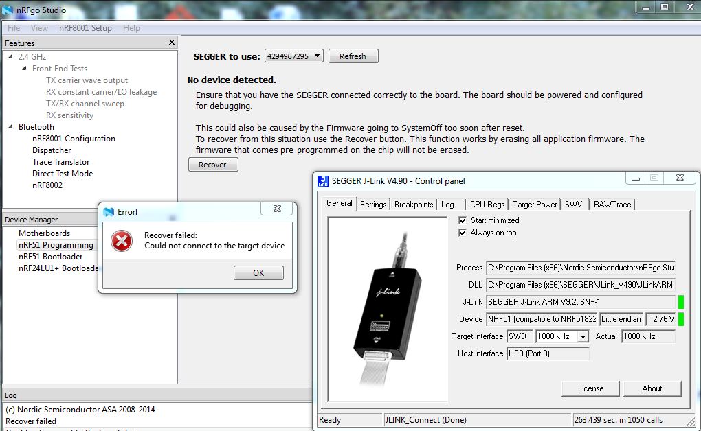
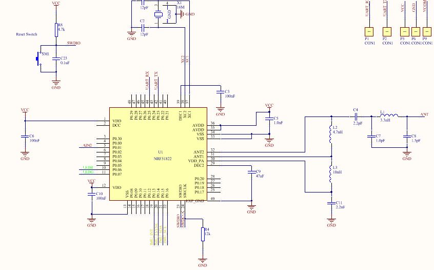
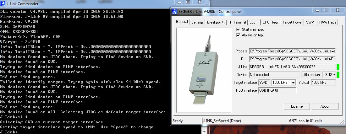
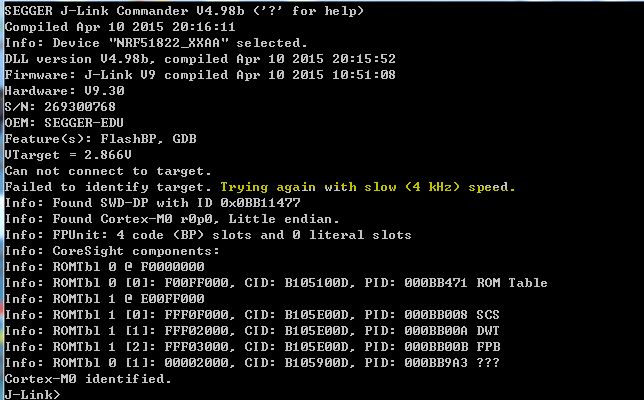
I want to bring up my own new board, but the nRFStudio can not connect to the J-Link, please check the picture. I connect 4 lines from board to J-Link, including VCC, GND, SWDIO, SWCLK, and I have already checked the signal of oscillator (16MHz), everything is fine, I do not know what I should do now, please help. P.S.If I click the Recover button, the ERROR dialog showed.

image description image description image description image description

  • Hi

    • Do you have a power supply on your board? The debugger is not capable of supplying power.
    • What nRF51 version and build number do you use? Some IC revisions requires an external pull down resistor on the SWDCLK line. See the Product anomaly document to find out which IC revisions are affected by this.
    • Are you absolutely sure that you have connected everything correctly? If you want us to have a look at your design feel free to contact us at our support portal at nordicsemi.com. (Or you can post your design here if you are comfortable with that)
    • Your J-Link driver seems to be somewhat outdated. Try to install the latest drivers: www.segger.com/jlink-software.html. You should also download the latest version of nRFgo Studio if you haven't already.
  • Thanks Martin, I have post the sch. The target have powered on using a cell battery and I checked the VCC already. The version is nRF51822 QFAAG2 and there is a 12k pull down resistor on the SWDCLK line. My J-Link can connect to a demo board normally, so maybe the driver is fine, I will update the driver of course. Thanks again.

  • Hi. As stated in the PAN document the nRF51822 QFAAG2 is not affected by the missing pull down and you should try to remove your external 12k resistor. You can also try to recover the J-Link following theses instructions. What kind of J-Link are you using?

  • What exact model of JLink do you have? The screenshot says JLink ARM but I never know if it shows the difference between ARM and ARM Lite and others. I think the ARM Lite needs 3v to work but the full JLink ARM, which I've never seen, works down to 1.8.

  • Hi, it is still not work after I remove the external 12k resistor, what's a pity. Because the J-Link can not scan the chip, the recover instructions are not available. I will use a new board to do some test today and will update status later. By the way, my J-Link is SEGGER OEM and I have already updated it to the latest version. Thanks.

Related