This post is older than 2 years and might not be relevant anymore
More Info: Consider searching for newer posts

SPI RAW Timing

These questions are in the context of using an nRF52840 in a serialization application. But I don't believe this will impact the information I am trying to understand. The following questions are in the context of using an nRF52840 for both the application and connectivity process. However, the customer's end product will use a 3rd party MCU fr the application processor.

Referring SPI RAW - packet writing, I have been asked what causes the approximate 10 uS delay from the end of the 2nd byte to /RDY transitioning to a high state. I assume this is simply overhead in the Slave or Master driver. What is bugging me is I am unable to determine is /RDY is responding to the /CD transition or an independent event with the slave.

Where can I find the timing information for SPIM NCS?  I would expect to see something similar information provided for the SPIS in section 6.26.6.2. Specifically, what is the timing from when the last bit is transmitted until CSN is deselected?

I think I understand the Slave's RDY transition in response to SPI_RAW_STATE_RX_HEADER or SPI_RAW_STATE_RX_PAYLOAD. But it's not clear is this because the buffer is filled if this the result NCS being deasserted. Please advise.

Can you provide a more detailed understanding of what causes the is 10 uS delay10 uS delay from the end of the 2nd byte to /RDY transitioning to a high state.

The customer payloads will vary in size and some will exceed 255 bytes. Can you point me to a reference as to how CS and RDY would or would not transition during a 770-byte data payload. To use the sterilization application, I assume that the application would imagine sending packets of 255 - 255- 255 - 5 in separate transactions? And CS and RDY would have the same timing as the SPI RAW - packet writing timing diagrams. But if one wrote an independent application, where the gold was to send one block of 770 bytes I suspect that CS will remain active for the whole transaction and READY would remain asserted as long as there is enough memory to store the receive data?

Thanks,

Jeff

  • Hi Jeff,

    Referring SPI RAW - packet writing, I have been asked what causes the approximate 10 uS delay from the end of the 2nd byte to /RDY transitioning to a high state. I assume this is simply overhead in the Slave or Master driver. What is bugging me is I am unable to determine is /RDY is responding to the /CD transition or an independent event with the slave.

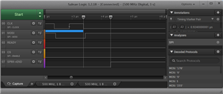
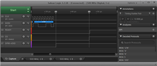
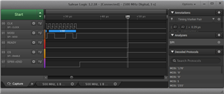
    The 10 us delay (or almost 15 us in my tests) seems to be a combination of multiple tasks:

    From last negedge on CLK to END event generated by SPIM peripheral (~1 us):

    From END event until CSN is deasserted (~13 us):

    From CSN is deasserted until RDY is deasserted (~0.3 us):

    The RDY signal is controlled by a PPI channel in the SPI slave transport layer:

    static void spi_slave_ppi_init(void)
    {
        uint32_t rdy_task = nrf_drv_gpiote_out_task_addr_get(m_spi_slave_raw_config.pin_rdy);
        //Configure PPI channel  to clear /RDY line
        NRF_PPI->CH[m_spi_slave_raw_config.ppi_rdy_ch].EEP = (uint32_t)(&SPI_SLAVE_REG->EVENTS_END);
        NRF_PPI->CH[m_spi_slave_raw_config.ppi_rdy_ch].TEP = rdy_task;
    
        //this works only for channels 0..15 - but soft device is using 8-15 anyway
        NRF_PPI->CHEN |= (1 << m_spi_slave_raw_config.ppi_rdy_ch);
        return;
    }

    It will be toggled when the END event is generated by the SPIS peripheral. This happens shortly after CSN is deassert by the SPI master:

    "When a granted transaction is completed and CSN goes high, the SPI slave will automatically release the semaphore and generate the END event."

    CSN is handled purely in software in the SPI driver used by the SPI master, only SPIM3 supports hardware control of SS/CSN pin. The main cause of the delay from the END event until CSN is deasserted seems to be the latency before the interrupt handler is triggered. I tried to reduce this delay by enabling constant latency mode, starting the HFCLK, and not putting the chip to sleep, but the only thing that helped was to run the debugger when testing.

    The customer payloads will vary in size and some will exceed 255 bytes. Can you point me to a reference as to how CS and RDY would or would not transition during a 770-byte data payload. To use the sterilization application, I assume that the application would imagine sending packets of 255 - 255- 255 - 5 in separate transactions? And CS and RDY would have the same timing as the SPI RAW - packet writing timing diagrams. But if one wrote an independent application, where the gold was to send one block of 770 bytes I suspect that CS will remain active for the whole transaction and READY would remain asserted as long as there is enough memory to store the receive data?

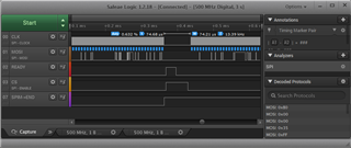
    I could not find any documentation describing this, but I checked with a logic analyzer that the CSN/RDY pins are toggled between each transfer of long packets:

    The serialization libraries was written when only nRF52832 chip was available. This chip had a limitation of 255 bytes length for most EasyDMA peripherals (SPIM/SPIS/TWIM/UARTE). I believe that the 255 byte packet limitation is originating from this. As mentioned above, the SPIS peripheral uses the CSN pin to determine when the transfer is ended. If the CSN pin was asserted during the whole transfer, the SPIS peripheral will not know when to prepare a new buffer. 

    nRF52840 has support for larger buffers (up to 65635 bytes) for both SPIM and SPIS, but unfortunately this is not implemented in the serialization libraries. Adding support for longer transfers would require rewriting the whole nrf_drv_spi/spis drivers (which uses uint8_t variables for the length parameters), or replace the drivers with nrfx variants. As far as I know, there is no plans to do this.

    Best regards,
    Jørgen

  • Hi Jørgen,

    Thank you for your investigation and thorough response.

    Cheers,

    Jeff

Related