Hello,
status = "okay";
};
compatible = "nordic,nrf-spim";
status = "okay";
sck-pin = <13>;
mosi-pin = <09>;
miso-pin = <40>;
};
Hello,
Hi learner,
In the NCS tutorial you can see how to add a ADC peripheral to your project.
For the .dts you could use "io-channels" as shown here.
Also here is a simple unofficial ADC sample that may be of help.
Hi Martin,
Thank you for your answer. I did go through the Tutorial Part 2 where the ADC is NOT configured via the .dts file. So, the idea of using io-channels in the .dts file is what I am interested in. I have read some of it and I am not sure I get it. So, I am going to have a go at changing the sample of the light intensity controller in Tutorial 2 and use the .dts file and see if I can get it to work. I will probably need your help at some point to get it to work.
Thank you for your support.
I have assumed that the number 4 in the line below is the pin number P0.04 which corresponds to adc channel AIN0. Is this right?
io-channels = <&adc0 4>;
Hi Learner,
Yes, that should be correct.
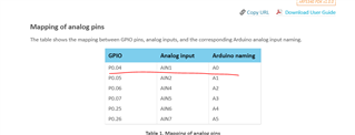
p0.04 of the nRF5340, so AIN1
https://infocenter.nordicsemi.com/index.jsp?topic=%2Fug_nrf5340_pdk%2FUG%2Fnrf5340_PDK%2Fhw_analog_pins.html
Hi Martin,
According to the PCA10095 schematics of the nRF5340 PDK (nRF5340-QKAA) pin 4 on P0.04 is AIN0 not AIN1.
Could you please double check. Thank you.
Kind regards
Mohamed
Hi Mohamed,
You are correct, there seems to be some difference in the User guide and the Schematic.
I will check this internally so it will be corrected.
Since the only inconsistency is the user guide, The correct Pin naming is the the schematic and the product spec. which states: P0.04 is AIN0
Thank you.
Thank you.