Hello,
I am developing a wireless sensing device using the nRF24L01+ module and I'm planning to use a u.FL connector in my design. I can't seem to find any manufacturer recommendations regarding correct board layout for a u.FL connector.
Board Layout Questions:
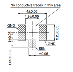
- Should I include a keep-out region under the antenna launch area under the (u.FL) connector?
- If a keep-out is recommended, should it be applied to all layers?
- Should I stitch the grounds of top and bottom layers to the RF Gnd (layer 2), or just the connect the Ground on the Top Layer to the RF ground plane and leave the bottom layer disconnected in this area?
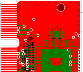
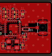
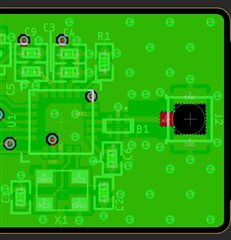
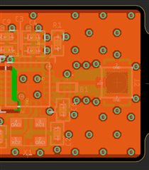
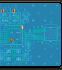
My current board layout is shown below with the following stackup:
- Layer 1 = Red (Signals / Gnd)
- Layer 2 = Green (Solid Gnd)
- Layer 3 = Orange (Power Planes)
- Layer 4 = Blue (two signals but mostly Gnd)
Your help is greatly appreciated