This post is older than 2 years and might not be relevant anymore
More Info: Consider searching for newer posts

"nrfjprog -e" renders our board unconfigurable

We have a custom PCB fitted with the nRF52840 SOC, we've previously erased and written to it via the nRF programmer tool. However, when trying to use the nrfjprog -e command it erases the board successfully but any subsequent attempts to reach the board (nrfjprog -e, nrfjprog --recover, or any command) produce the following error: 

ERROR: nrfjprog could not identify the target device. This may be due to an
ERROR: invalid family argument, a problem with your device, or nrfjprog may
ERROR: not yet support your device.
ERROR: Please check the family argument passed, or upgrade nrfjprog to a more
ERROR: recent version.

Trying to configure with the programmer tool produces: 

Could not fetch memory size of target devkit: Error: Error occured when get library info. Errorcode: CouldNotOpenDevice (0x4) Lowlevel error: Unknown value (fffffffa)

Same goes for compilation attempts via Segger or VScode. 

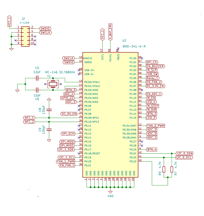
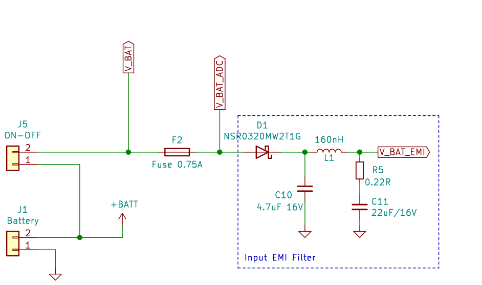
  • We're using the Segger Jlink to communicate with the board via SWCLK and SWDIO, it is also feeding VCC but the board's power is dependent on a LiPo 3.7V battery via ADC. 
  • We've been rewriting, erasing, compiling etc. on this board for a long time and have never encountered this issue until the moment we used nrfjprog -e
  • An attempt to use the command on another custom board produced the same results. 
  • An attempt to use the command on the nRF52840 DK and an Adafruit board caused no errors and everything seems to be working fine. 
  • Reset pin on the custom PCB is unavailable so that's not an option. 

So obviously the problem is with our custom board, any suggestions, apart from not using the command again?

  • Hi,

    My initial suspicion is that your design is not using the default output value of REG0 which is 1.8V. A nrfjprog --eraseall command will erase everything from the IC including the UICR. The UICR contains the REG0 register which sets the output of the first regulator. Are you using the board in High voltage mode and have you configured REG0 to something else then the default value?

    regards

    Jared 

  • Your suspicion is spot on. We did set the board in High voltage mode prior to using erase. We set REG0 with the command:

    nrfjprog --memwr 0x10001304 (UICR.REGOUT0 address) --val 0xFFFFFFFD (3V3 setting)

    Trying to set it after erase results in:

    ERROR: Low voltage detected at the target. Please make sure the device is
    ERROR: properly supplied.

    So, what do you suggest doing?

  • Hmm.. 

    So you're not managing to write to the UICR after the erase, and you're still not able to identify the board with nrfjprog? How is your custom board dependent on the VDD being 3V3? What happens when REG0 is 1.8V, is there some external part on your board that is supplied by the REG0 output of the nRF52840? Would not supplying this properly block SWD from communication with nRF52840 on your board? As you can tell, I could need a better overview of your board, a Schematic would help alot!

    ToBe said:
    We did set the board in High voltage mode prior to using erase

    How was the board configured when you initially programmed it? Normal mode? Is there an option to short VDD and VDDH which would effectively set the board in Normal mode and then flash the application that writes to the REG0 register? 

    regards

    Jared

  • Which J-link model are you using? Maybe it can't program DUTs at 1V8. It doesn't seem that you have anything that is dependent on the voltage being 3V3 in your design that would hinder re-flashing. 

    Could you try shorting VDD and VDDH (configure the board in Normal mode) and supply the device directly with 3V3, which is still within Normal mode conditions. Then proceed with programming the board with an application that writes to the UICR?

    regards

    Jared 

Related