
mpu6050 connections
vcc-->vdd
gnd-->gnd
scl-->pin 27
sda-->pin 26
Main.c
#include <stdio.h>
#include "boards.h"
#include "app_util_platform.h"
#include "app_error.h"
#include "nrf_drv_twi.h"
#include "mpu6050.h"
#include "nrf_log.h"
#include "nrf_log_ctrl.h"
#include "nrf_log_default_backends.h"
// main code
int main(void)
{
// initialize the logger
APP_ERROR_CHECK(NRF_LOG_INIT(NULL));
NRF_LOG_DEFAULT_BACKENDS_INIT();
// create arrays which will hold x,y & z co-ordinates values of acc and gyro
static int16_t AccValue[3], GyroValue[3];
bsp_board_init(BSP_INIT_LEDS | BSP_INIT_BUTTONS); // initialize the leds and buttons
twi_master_init(); // initialize the twi
nrf_delay_ms(1000); // give some delay
while(mpu6050_init() == false) // wait until MPU6050 sensor is successfully initialized
{
NRF_LOG_INFO("MPU_6050 initialization failed!!!"); // if it failed to initialize then print a message
nrf_delay_ms(1000);
}
NRF_LOG_INFO("MPU6050 Init Successfully!!!");
NRF_LOG_INFO("Reading Values from ACC & GYRO"); // display a message to let the user know that the device is starting to read the values
nrf_delay_ms(2000);
while (true)
{
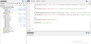
if(MPU6050_ReadAcc(&AccValue[0], &AccValue[1], &AccValue[2]) == true) // Read acc value from mpu6050 internal registers and save them in the array
{
NRF_LOG_INFO("ACC Values: x = %d y = %d z = %d", AccValue[0], AccValue[1], AccValue[2]); // display the read values
}
else
{
NRF_LOG_INFO("Reading ACC values Failed!!!"); // if reading was unsuccessful then let the user know about it
}
if(MPU6050_ReadGyro(&GyroValue[0], &GyroValue[1], &GyroValue[2]) == true) // read the gyro values from mpu6050's internal registers and save them in another array
{
NRF_LOG_INFO("GYRO Values: x = %d y = %d z = %d", GyroValue[0], GyroValue[1], GyroValue[2]); // display then values
}
else
{
NRF_LOG_INFO("Reading GYRO values Failed!!!");
}
nrf_delay_ms(100); // give some delay
}
}
/** @} */
mpu6050.h
#ifndef AT24C02_H__
#define AT24C02_H__
#include "nrf_delay.h"

//I2C Pins Settings, you change them to any other pins
#define TWI_SCL_M           27         //I2C SCL Pin
#define TWI_SDA_M           26         //I2C SDA Pin


#define MPU6050_ADDRESS_LEN  1         //MPU6050
#define MPU6050_ADDRESS     (0xD0>>1)  //MPU6050 Device Address
#define MPU6050_WHO_AM_I     0x68U     //MPU6050 ID


#define MPU6050_GYRO_OUT        0x43
#define MPU6050_ACC_OUT         0x3B

#define ADDRESS_WHO_AM_I          (0x75U) //  WHO_AM_I register identifies the device. Expected value is 0x68.
#define ADDRESS_SIGNAL_PATH_RESET (0x68U) //

//MPU6050 Registers addresses, see datasheet for more info and each register's function
#define MPU_SELF_TESTX_REG		0x0D
#define MPU_SELF_TESTY_REG		0x0E
#define MPU_SELF_TESTZ_REG		0x0F
#define MPU_SELF_TESTA_REG		0x10
#define MPU_SAMPLE_RATE_REG		0x19
#define MPU_CFG_REG                     0x1A
#define MPU_GYRO_CFG_REG		0x1B
#define MPU_ACCEL_CFG_REG		0x1C
#define MPU_MOTION_DET_REG		0x1F
#define MPU_FIFO_EN_REG			0x23
#define MPU_I2CMST_CTRL_REG		0x24
#define MPU_I2CSLV0_ADDR_REG            0x25
#define MPU_I2CSLV0_REG			0x26
#define MPU_I2CSLV0_CTRL_REG            0x27
#define MPU_I2CSLV1_ADDR_REG            0x28
#define MPU_I2CSLV1_REG			0x29
#define MPU_I2CSLV1_CTRL_REG            0x2A
#define MPU_I2CSLV2_ADDR_REG            0x2B
#define MPU_I2CSLV2_REG			0x2C
#define MPU_I2CSLV2_CTRL_REG            0x2D
#define MPU_I2CSLV3_ADDR_REG            0x2E
#define MPU_I2CSLV3_REG			0x2F
#define MPU_I2CSLV3_CTRL_REG            0x30
#define MPU_I2CSLV4_ADDR_REG            0x31
#define MPU_I2CSLV4_REG			0x32
#define MPU_I2CSLV4_DO_REG		0x33
#define MPU_I2CSLV4_CTRL_REG            0x34
#define MPU_I2CSLV4_DI_REG		0x35


#define MPU_PWR_MGMT1_REG		0x6B
#define MPU_PWR_MGMT2_REG		0x6C

#define MPU_I2CMST_STA_REG		0x36
#define MPU_INTBP_CFG_REG		0x37
#define MPU_INT_EN_REG			0x38
#define MPU_INT_STA_REG			0x3A

#define MPU_I2CMST_DELAY_REG            0x67
#define MPU_SIGPATH_RST_REG		0x68
#define MPU_MDETECT_CTRL_REG            0x69
#define MPU_USER_CTRL_REG		0x6A
#define MPU_PWR_MGMT1_REG		0x6B
#define MPU_PWR_MGMT2_REG		0x6C
#define MPU_FIFO_CNTH_REG		0x72
#define MPU_FIFO_CNTL_REG		0x73
#define MPU_FIFO_RW_REG			0x74
#define MPU_DEVICE_ID_REG		0x75

void twi_master_init(void); // initialize the twi communication
bool mpu6050_init(void);    // initialize the mpu6050

/**
  @brief Function for writing a MPU6050 register contents over TWI.
  @param[in]  register_address Register address to start writing to
  @param[in] value Value to write to register
  @retval true Register write succeeded
  @retval false Register write failed
*/
bool mpu6050_register_write(uint8_t register_address, const uint8_t value);

/**
  @brief Function for reading MPU6050 register contents over TWI.
  Reads one or more consecutive registers.
  @param[in]  register_address Register address to start reading from
  @param[in]  number_of_bytes Number of bytes to read
  @param[out] destination Pointer to a data buffer where read data will be stored
  @retval true Register read succeeded
  @retval false Register read failed
*/
bool mpu6050_register_read(uint8_t register_address, uint8_t *destination, uint8_t number_of_bytes);

/**
  @brief Function for reading and verifying MPU6050 product ID.
  @retval true Product ID is what was expected
  @retval false Product ID was not what was expected
*/
bool mpu6050_verify_product_id(void);


bool MPU6050_ReadGyro(int16_t *pGYRO_X , int16_t *pGYRO_Y , int16_t *pGYRO_Z );
bool MPU6050_ReadAcc( int16_t *pACC_X , int16_t *pACC_Y , int16_t *pACC_Z );

#endif
mpu6050.c
#include <stdbool.h>
#include <stdint.h>
#include <string.h>
#include "nrf_drv_twi.h"
#include "mpu6050.h"
//Initializing TWI0 instance
#define TWI_INSTANCE_ID 0
// A flag to indicate the transfer state
static volatile bool m_xfer_done = false;
// Create a Handle for the twi communication
static const nrf_drv_twi_t m_twi = NRF_DRV_TWI_INSTANCE(TWI_INSTANCE_ID);
//Event Handler
void twi_handler(nrf_drv_twi_evt_t const * p_event, void * p_context)
{
//Check the event to see what type of event occurred
switch (p_event->type)
{
//If data transmission or receiving is finished
case NRF_DRV_TWI_EVT_DONE:
m_xfer_done = true;//Set the flag
break;
default:
// do nothing
break;
}
}
//Initialize the TWI as Master device
void twi_master_init(void)
{
ret_code_t err_code;
// Configure the settings for twi communication
const nrf_drv_twi_config_t twi_config = {
.scl = TWI_SCL_M, //SCL Pin
.sda = TWI_SDA_M, //SDA Pin
.frequency = NRF_DRV_TWI_FREQ_400K, //Communication Speed
.interrupt_priority = APP_IRQ_PRIORITY_HIGH, //Interrupt Priority(Note: if using Bluetooth then select priority carefully)
.clear_bus_init = false //automatically clear bus
};
//A function to initialize the twi communication
err_code = nrf_drv_twi_init(&m_twi, &twi_config, twi_handler, NULL);
APP_ERROR_CHECK(err_code);
//Enable the TWI Communication
nrf_drv_twi_enable(&m_twi);
}
/*
A function to write a Single Byte to MPU6050's internal Register
*/
bool mpu6050_register_write(uint8_t register_address, uint8_t value)
{
ret_code_t err_code;
uint8_t tx_buf[MPU6050_ADDRESS_LEN+1];
//Write the register address and data into transmit buffer
tx_buf[0] = register_address;
tx_buf[1] = value;
//Set the flag to false to show the transmission is not yet completed
m_xfer_done = false;
//Transmit the data over TWI Bus
err_code = nrf_drv_twi_tx(&m_twi, MPU6050_ADDRESS, tx_buf, MPU6050_ADDRESS_LEN+1, false);
//Wait until the transmission of the data is finished
while (m_xfer_done == false)
{
}
// if there is no error then return true else return false
if (NRF_SUCCESS != err_code)
{
return false;
}
return true;
}
/*
A Function to read data from the MPU6050
*/
bool mpu6050_register_read(uint8_t register_address, uint8_t * destination, uint8_t number_of_bytes)
{
ret_code_t err_code;
//Set the flag to false to show the receiving is not yet completed
m_xfer_done = false;
// Send the Register address where we want to write the data
err_code = nrf_drv_twi_tx(&m_twi, MPU6050_ADDRESS, ®ister_address, 1, true);
//Wait for the transmission to get completed
while (m_xfer_done == false){}
// If transmission was not successful, exit the function with false as return value
if (NRF_SUCCESS != err_code)
{
return false;
}
//set the flag again so that we can read data from the MPU6050's internal register
m_xfer_done = false;
// Receive the data from the MPU6050
err_code = nrf_drv_twi_rx(&m_twi, MPU6050_ADDRESS, destination, number_of_bytes);
//wait until the transmission is completed
while (m_xfer_done == false){}
// if data was successfully read, return true else return false
if (NRF_SUCCESS != err_code)
{
return false;
}
return true;
}
/*
A Function to verify the product id
(its a basic test to check if we are communicating with the right slave, every type of I2C Device has
a special WHO_AM_I register which holds a specific value, we can read it from the MPU6050 or any device
to confirm we are communicating with the right device)
*/
bool mpu6050_verify_product_id(void)
{
uint8_t who_am_i; // create a variable to hold the who am i value
// Note: All the register addresses including WHO_AM_I are declared in
// MPU6050.h file, you can check these addresses and values from the
// datasheet of your slave device.
if (mpu6050_register_read(ADDRESS_WHO_AM_I, &who_am_i, 1))
{
if (who_am_i != MPU6050_WHO_AM_I)
{
return false;
}
else
{
return true;
}
}
else
{
return false;
}
}
/*
Function to initialize the mpu6050
*/
bool mpu6050_init(void)
{
bool transfer_succeeded = true;
//Check the id to confirm that we are communicating with the right device
transfer_succeeded &= mpu6050_verify_product_id();
if(mpu6050_verify_product_id() == false)
{
return false;
}
// Set the registers with the required values, see the datasheet to get a good idea of these values
(void)mpu6050_register_write(MPU_PWR_MGMT1_REG , 0x00);
(void)mpu6050_register_write(MPU_SAMPLE_RATE_REG , 0x07);
(void)mpu6050_register_write(MPU_CFG_REG , 0x06);
(void)mpu6050_register_write(MPU_INT_EN_REG, 0x00);
(void)mpu6050_register_write(MPU_GYRO_CFG_REG , 0x18);
(void)mpu6050_register_write(MPU_ACCEL_CFG_REG,0x00);
return transfer_succeeded;
}
/*
Read the Gyro values from the MPU6050's internal Registers
*/
bool MPU6050_ReadGyro(int16_t *pGYRO_X , int16_t *pGYRO_Y , int16_t *pGYRO_Z )
{
uint8_t buf[6];
bool ret = false;
if(mpu6050_register_read(MPU6050_GYRO_OUT, buf, 6) == true)
{
*pGYRO_X = (buf[0] << 8) | buf[1];
if(*pGYRO_X & 0x8000) *pGYRO_X-=65536;
*pGYRO_Y= (buf[2] << 8) | buf[3];
if(*pGYRO_Y & 0x8000) *pGYRO_Y-=65536;
*pGYRO_Z = (buf[4] << 8) | buf[5];
if(*pGYRO_Z & 0x8000) *pGYRO_Z-=65536;
ret = true;
}
return ret;
}
/*
A Function to read accelerometer's values from the internal registers of MPU6050
*/
bool MPU6050_ReadAcc( int16_t *pACC_X , int16_t *pACC_Y , int16_t *pACC_Z )
{
uint8_t buf[6];
bool ret = false;
if(mpu6050_register_read(MPU6050_ACC_OUT, buf, 6) == true)
{
mpu6050_register_read(MPU6050_ACC_OUT, buf, 6);
*pACC_X = (buf[0] << 8) | buf[1];
if(*pACC_X & 0x8000) *pACC_X-=65536;
*pACC_Y= (buf[2] << 8) | buf[3];
if(*pACC_Y & 0x8000) *pACC_Y-=65536;
*pACC_Z = (buf[4] << 8) | buf[5];
if(*pACC_Z & 0x8000) *pACC_Z-=65536;
ret = true;
}
return ret;
}
i also tried in putty, but nothing is showing in the terminal
any answers, without hesitation ask any question.

