This post is older than 2 years and might not be relevant anymore
More Info: Consider searching for newer posts

Direction Finding Phase Shift Between Reference Period And First Slot

Hi,

When I tried to use BLE5.1 phase data to achieve direction finding, I found a phase shift between reference period and the first slot, as the below graph shown:

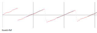
The range of y-axis is 2 Pi. The antenna used for the reference period and the first slot is the same, but there is a phase shift of around 1 Pi ( a half of period ). I have tried for several different angles and all phase shifts are similar. I saw a paper that uses different antennas in reference period and the first slot to calculate the angle, so the extra phase shift should not happen. Will it affect the calculation of subsequent data? If it will, how can I solve this or put it into calculation?

Best Regards,

Fan

Parents
  • Hello Fan, 

    Can you please elaborate on your setup? What is the reference point? Have a look at our white paper of direction finding

    Unfortunately, this is all we have. 

    Kind regards,
    Øyvind

  • Hi Øyvind,

    Thank you for replying. Here is my setup of radio:

    NRF_RADIO->MODE = RADIO_MODE_MODE_Ble_1Mbit;
    NRF_RADIO->CTEINLINECONF = RADIO_CTEINLINECONF_CTEINLINECTRLEN_Disabled;
    NRF_RADIO->DFEPACKET.MAXCNT = 1250;
    NRF_RADIO->PSEL.DFEGPIO[0] = ANT1;
    NRF_RADIO->PSEL.DFEGPIO[1] = ANT0;
    NRF_RADIO->CLEARPATTERN = 3;
    NRF_RADIO->SWITCHPATTERN = 3;
    NRF_RADIO->SWITCHPATTERN = 3;
    NRF_RADIO->SWITCHPATTERN = 3;
    NRF_RADIO->SWITCHPATTERN = 3;
    NRF_RADIO->SWITCHPATTERN = 3;
    NRF_RADIO->SWITCHPATTERN = 3;
    NRF_RADIO->SWITCHPATTERN = 1;
    NRF_RADIO->SWITCHPATTERN = 1;
    NRF_RADIO->SWITCHPATTERN = 1;
    NRF_RADIO->SWITCHPATTERN = 1;
    NRF_RADIO->PACKETPTR = (uint32_t)&packet;
    NRF_RADIO->DFEMODE = RADIO_DFEMODE_DFEOPMODE_AoA;
    NRF_RADIO->DFECTRL1 = 20 << RADIO_DFECTRL1_NUMBEROF8US_Pos
    | 1 << RADIO_DFECTRL1_DFEINEXTENSION_Pos
    | RADIO_DFECTRL1_SAMPLETYPE_MagPhase << RADIO_DFECTRL1_SAMPLETYPE_Pos
    | RADIO_DFECTRL1_TSWITCHSPACING_4us << RADIO_DFECTRL1_TSWITCHSPACING_Pos
    | RADIO_DFECTRL1_TSAMPLESPACINGREF_125ns << RADIO_DFECTRL1_TSAMPLESPACINGREF_Pos
    | RADIO_DFECTRL1_TSAMPLESPACING_125ns << RADIO_DFECTRL1_TSAMPLESPACING_Pos;
    NRF_RADIO->DFEPACKET.PTR = (uint32_t)&rfRaws;

    The phase graph is after processed. I made the gap between all adjacent phases less than half the period so the curve will be continuous. And I used the linear regression line as the reference, and got the final curve as the above image shows.

    Could you please provide a typical phase and magnitude graph as a reference? Currently I can get the IQ sample data, but it's not stable. There are too many possible issues that can cause this, like RF switch, antenna or programming, so I need some way to debug with it.

    Best Regards,

    Fan

  • Thank you Dmitry. From your answer and the document, the reference period is correct and not a issue.

    The unstable means the phase shifting and angle will change from time to time. I just did a test and get these phase differences: 93, 93, 90, 94, 79, 95, 103, 103, 103, 99, 95, 110, 104, 98, 106, 87, 100, 94. The maximum is 110 and the minimum is 79, for two antennas with 6.25cm distance, it's 33 degree and 23 degree ( but actually my angle is set to 75 degree ). I don't know how to calibrate with the data, if I just add a fixed delta to make the average angle to 75 degree ( phase diff 194 ), the 110 and 79 will become around 210 and 179, and now the angle is around 90 degree and 63 degree, which cannot be used.

    Thank you for the information about the multipath reflection, can it be detected by the magnitude data? I will have a try. And also for the antenna array, I will reconsider it to avoid degree near 90.

  • What antenna are you using? The figure you have attached does not give much information I'm afraid. 

    You need to measure the phase on all antennas against the reference slot. The reference phase should not be static, as the frequency on transmitter and receiver are not the same. The phase will drift in a linear fashion. 

    Kind regards,
    Øyvind

  • The unstable means the phase shifting and angle will change from time to time. I just did a test and get these phase differences: 93, 93, 90, 94, 79, 95, 103, 103, 103, 99, 95, 110, 104, 98, 106, 87, 100, 94.

    If you're testing in a noisy enwironment, it's quite expected. You need to filter results, dropping the ones with large difference from the mean value. I would suggest to take an experiment outdoors, away from wifi networks and other sources of noise, to ensure that hardware is working properly.
    To get better results, try to shorten the slots as much as response time of RF switch allows (16 us is too much - crystal jitter may influent the results), and take a single sample from each slot close to its end.

    for two antennas with 6.25cm distance, it's 33 degree and 23 degree ( but actually my angle is set to 75 degree )

    Did you take into account trace lengths from RF switch to antennas? For evaluation stage, I would not look at absolute values at all - all you need is to figure out the range when results are stable, then create a phase-to-angle mapping.

    Thank you for the information about the multipath reflection, can it be detected by the magnitude data?

    Multipath reflections can be mitigated by a multi-element array and spatial spectrum estimation algorithm, such as MUSIC or MVDR. With two antennas, there is not enough information to detect multiple paths.

  • Thank you Øyvind. I designed 3 antennas placed on 3 corners of a square. But now I only use 2 of them to test. I think I have taken the frequency into count, I calculated the average slope of all period and use it as the real frequency, as the black line in the figure shown.

  • Thank you Dmitry.

    For the 16us slot, I set it because I found the phase graph is not very stable near the switch slot. I will try your suggestion, the way is much easier than what I'm using now.

    On the PCB board, I set all trace lengths to be almost the same. For the phase-to-angle mapping, that's a good idea and I will have a try. 

    Put more antennas into array is also in the next step's plan. Thank you for providing the algorithm, now I can do some research on it :)

Reply
  • Thank you Dmitry.

    For the 16us slot, I set it because I found the phase graph is not very stable near the switch slot. I will try your suggestion, the way is much easier than what I'm using now.

    On the PCB board, I set all trace lengths to be almost the same. For the phase-to-angle mapping, that's a good idea and I will have a try. 

    Put more antennas into array is also in the next step's plan. Thank you for providing the algorithm, now I can do some research on it :)

Children
No Data
Related