This post is older than 2 years and might not be relevant anymore
More Info: Consider searching for newer posts
This discussion has been locked.
You can no longer post new replies to this discussion. If you have a question you can start a new discussion

Correct wiring for programming external module with nRF51-DK (and Keil)

Hello,

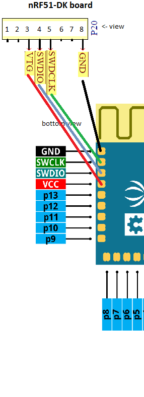
Is this the correct setup? What else will I need to do to make it work (e.g. it says something about the MCU will detect the external board and then programm/debug it automatically, when it detects the supply voltage. So the VTG does not deliver but expect 3V? Can I just connect it with the VDD next to the Boot/Reset Button? To supply the external board and make the MCU recognize it?)

image description

Parents
  • Hi! You can use P19 or P20. The Vtg (aka Vref) is only used to detect a voltage on the target board. This is how your nRF51 DK knows an external board is present. From the J-Link manual:

    This is the target reference voltage. It is used to check if the target has power, to create the logic-level reference for the input comparators and to control the output logic levels to the target. It is normally fed from Vdd of the target board and must not have a series resistor.

    It is perfectly fine to use the VDD pins on the nRF51 DK to provide power to your target (assuming the target needs 3 volts).

  • EDIT: Sorry, I was mistaken. You can use P20 as well. It is an additional connector meant for shields with a different pinout standard. I updated my answer above.

Reply Children
No Data
Related