Hello, guys,
We are designing our custom board that contains nRF9160 SiP.
I would like to ask some questions here concerning programming/debugging nRF9160 SiP on the custom board.
We know it is possible to use nRF9160-DK as a programmer
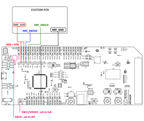
- Is this all we need for programming and debugging nRF9160 SiP on our custom board? Do we need to include a nRESET pin as well?
- Can we update the LTE modem as well with the above approach?
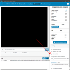
- Do we need some USB/UART converter (that supports 1.8V voltage level because our GPIO level on nRF9160 will be 1.8V) for being able to benefit from LTE Link Monitor and send AT Commands to the modem?
- Is there any advantage of using JLink Base programmer/debugger over nRF9160-DK?
Thanks in advance for your time and efforts.
Cheers,
Bojan.