This post is older than 2 years and might not be relevant anymore
More Info: Consider searching for newer posts

nRF Connect SDK: SPI communication is not working on nRF52840 dev kit

Hi nRF support team,

By using the nRF Connect SDK, I am trying to implement an SPI communication with the display module from my nRF52840 dev kit and nRF52840 as a master.
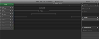
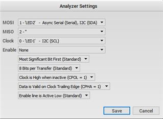
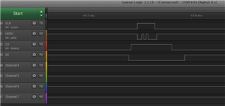
I have tried below test code. But I m not receiving invalid data on MOSI pin and also not receiving a proper clock signal.

Can you please share the working sample code of SPI as a master of nRFconnect SDK?

This is my .overlay configuration:
&spi3 {
    status = "okay";
    cs-gpios = <&gpio0 12 0>;

    stxxxx@0 {
        compatible = "sitronix,stxxxx";
        label = "STxxxx";
        spi-max-frequency = <2000000>;
        reg = <0>;
        };
};

nRFsdk Pin configuration:
CS  <-> P0.12
CLK <-> P1.15
MISO <-> P1.14
MOSI <-> P1.13


Test Code:
struct device *spi_dev;
struct spi_cs_control spi_cs;
        
const struct spi_config spi_cfg = {
    .operation = SPI_OP_MODE_MASTER | SPI_WORD_SET(8) | SPI_TRANSFER_MSB |
             SPI_MODE_CPOL | SPI_MODE_CPHA,
    .frequency = 2000000,
    //.slave = 0,
};

static void spi_init(void)
{

    spi_cs.gpio_dev = device_get_binding("STxxxx");
           spi_cs.gpio_pin = DT_INST_SPI_DEV_CS_GPIOS_PIN(0);
    spi_cs.delay = 0;
        spi_cs.gpio_dt_flags = GPIO_ACTIVE_LOW;
       
    //spi_cfg.cs = &spi_cs;


        printk("SPI Initiating...");
    spi_dev = device_get_binding("STxxxx");
    if (spi_dev == NULL) {
        printk("\n******* Display device not found.  Aborting test. *******\n");
        return;
    }
}

void spi_send(struct device *spi_dev)
{
    int err;
    static uint8_t tx_buffer[1];
    static uint8_t rx_buffer[1];

    const struct spi_buf tx_buf = {
        .buf = tx_buffer,
        .len = sizeof(tx_buffer)
    };
    const struct spi_buf_set tx = {
        .buffers = &tx_buf,
        .count = 1
    };

    struct spi_buf rx_buf = {
        .buf = rx_buffer,
        .len = sizeof(rx_buffer),
    };
    const struct spi_buf_set rx = {
        .buffers = &rx_buf,
        .count = 1
    };
    err = spi_transceive(spi_dev, &spi_cfg, &tx, &rx);
    if (err) {
        printk("SPI write error: %d\n", err);
    } else {
        /* Connect MISO to MOSI for loopback */
        printk("MISO TX sent: %x\n", tx_buffer[0]);
        printk("MOSI RX recv: %x\n", rx_buffer[0]);
    }    
            
}

void main(void)
{  
        printk("\n**** main() start... ****\n");
        //Initlize the SPI module
        spi_init();
    
        while (1)
    {
              spi_send(spi_dev);
              k_sleep(K_SECONDS(2));
    }
}

Thanks in advance.
Regards,
Kalyan

Parents Reply Children
  • Hi Edvin,

    Thanks for the suggestion. Now I am able to see the proper clock coming on SCK pin but not seeing valid data received on the MOSI pin.

    For your information, I have tried to transmit one byte '?' (x3f) data and expected to receive MOSI data signal should be 00111111 but I have received 00101000 which is not correct. Can you please let me know if anything I have missed in the SPI configuration and test code?

    Thanks in advance.

    Regards,

    Kalyan

  • Are you sure you didn't change the SPI config?

    What happens if you try the following main.c file:

    /*
    * Copyright (c) 2012-2014 Wind River Systems, Inc.
    *
    * SPDX-License-Identifier: Apache-2.0
    */
    
    #include <zephyr.h>
    #include <sys/printk.h>
    #include <drivers/spi.h>
    #include <drivers/gpio.h>
    
    #define LED_PIN 16
    #define SS_PIN 31
    
    #define TEST_STRING "Southic"
    
    static const struct spi_config spi_cfg = {
    	.operation = SPI_OP_MODE_MASTER | SPI_WORD_SET(8) | SPI_TRANSFER_MSB |
    		     SPI_MODE_CPOL | SPI_MODE_CPHA,
    	.frequency = 4000000,
    	.slave = 0,
    };
    
    struct device * spi_dev;
    
    static void spi_init(void)
    {
    	const char* const spiName = "SPI_1";
    	spi_dev = device_get_binding(spiName);
    
    	if (spi_dev == NULL) {
    		printk("Could not get %s device\n", spiName);
    		return;
    	}
    }
    
    void spi_test_send(void)
    {
    	int err;
    	static u8_t tx_buffer[8] = TEST_STRING;
    	static u8_t rx_buffer[8];
    
    	tx_buffer[0] = 0x3f;
    	
    	for (int i=0; i<sizeof(tx_buffer);i++)
    	{
    		//tx_buffer[i] = 0x61 + i;
    		rx_buffer[i] = 0x00;
    	}
    
    	const struct spi_buf tx_buf = {
    		.buf = tx_buffer,
    		.len = sizeof(tx_buffer)
    	};
    	const struct spi_buf_set tx = {
    		.buffers = &tx_buf,
    		.count = 1
    	};
    
    	struct spi_buf rx_buf = {
    		.buf = rx_buffer,
    		.len = sizeof(rx_buffer),
    	};
    	const struct spi_buf_set rx = {
    		.buffers = &rx_buf,
    		.count = 1
    	};
    	
    	err = spi_transceive(spi_dev, &spi_cfg, &tx, &rx);
    	
    	if (err) {
    		printk("SPI error: %d\n", err);
    	} else {
    		/* Connect MISO to MOSI for loopback */
    		printk("TX sent: ");
    		for (uint8_t i=0; i<6; i++)
    		{
    			printk("%x", tx_buffer[i]);
    		}
    		printk("\r\nRX recv: ");
    		for (uint8_t i=0; i<6; i++)
    		{
    			printk("%c", rx_buffer[i]);
    		}
    		printk("\r\n");
    		//tx_buffer[0]++;
    	}	
    }
    
    void main(void)
    {
    	int ret;
    	bool my_bool = false;
    
    	struct device * dev = device_get_binding("GPIO_0");
    	if (!dev) {
    		printk("Device not found\n");
    		return;
    	}
    	ret = gpio_pin_configure(dev, LED_PIN, GPIO_OUTPUT_ACTIVE);
    	if (ret < 0)
    	{
    		printk("failed %d", ret);
    	}
    	ret = gpio_pin_configure(dev, SS_PIN, GPIO_OUTPUT_ACTIVE);
    	if (ret <0)
    	{
    		printk("failed %d", ret);
    	}
    	printk("SPIM Example\n");
    	
    	spi_init();
    	
    
    	while (1) {
    		gpio_pin_set(dev, LED_PIN, my_bool);
    		
    		my_bool = !my_bool;
    		printk("my_bool %d\r\n", my_bool);
    		gpio_pin_set(dev, SS_PIN, false);
    		spi_test_send();
    		gpio_pin_set(dev, SS_PIN, true);
    		k_sleep(K_MSEC(1000));
    	}
    }

    (you can remove the LED pin output if you like. I used this for testing, and it prints "?outhic".

    Does it do that for you as well? You should see it in the logic analyzer. Try to enable the following settings:

    But with your own channels for mosi, miso and clock. 

    BR,

    Edvin

  • Hi Edvin,

    Thanks for the quick response and changes.

    I have connected CS to GND and now I am receiving the valid data on MOSI.

    Regards,

    Kalyan

Related