This post is older than 2 years and might not be relevant anymore
More Info: Consider searching for newer posts

nRF Connect SDK: SPI communication is not working on nRF52840 dev kit

Hi nRF support team,

By using the nRF Connect SDK, I am trying to implement an SPI communication with the display module from my nRF52840 dev kit and nRF52840 as a master.
I have tried below test code. But I m not receiving invalid data on MOSI pin and also not receiving a proper clock signal.

Can you please share the working sample code of SPI as a master of nRFconnect SDK?

This is my .overlay configuration:
&spi3 {
    status = "okay";
    cs-gpios = <&gpio0 12 0>;

    stxxxx@0 {
        compatible = "sitronix,stxxxx";
        label = "STxxxx";
        spi-max-frequency = <2000000>;
        reg = <0>;
        };
};

nRFsdk Pin configuration:
CS  <-> P0.12
CLK <-> P1.15
MISO <-> P1.14
MOSI <-> P1.13


Test Code:
struct device *spi_dev;
struct spi_cs_control spi_cs;
        
const struct spi_config spi_cfg = {
    .operation = SPI_OP_MODE_MASTER | SPI_WORD_SET(8) | SPI_TRANSFER_MSB |
             SPI_MODE_CPOL | SPI_MODE_CPHA,
    .frequency = 2000000,
    //.slave = 0,
};

static void spi_init(void)
{

    spi_cs.gpio_dev = device_get_binding("STxxxx");
           spi_cs.gpio_pin = DT_INST_SPI_DEV_CS_GPIOS_PIN(0);
    spi_cs.delay = 0;
        spi_cs.gpio_dt_flags = GPIO_ACTIVE_LOW;
       
    //spi_cfg.cs = &spi_cs;


        printk("SPI Initiating...");
    spi_dev = device_get_binding("STxxxx");
    if (spi_dev == NULL) {
        printk("\n******* Display device not found.  Aborting test. *******\n");
        return;
    }
}

void spi_send(struct device *spi_dev)
{
    int err;
    static uint8_t tx_buffer[1];
    static uint8_t rx_buffer[1];

    const struct spi_buf tx_buf = {
        .buf = tx_buffer,
        .len = sizeof(tx_buffer)
    };
    const struct spi_buf_set tx = {
        .buffers = &tx_buf,
        .count = 1
    };

    struct spi_buf rx_buf = {
        .buf = rx_buffer,
        .len = sizeof(rx_buffer),
    };
    const struct spi_buf_set rx = {
        .buffers = &rx_buf,
        .count = 1
    };
    err = spi_transceive(spi_dev, &spi_cfg, &tx, &rx);
    if (err) {
        printk("SPI write error: %d\n", err);
    } else {
        /* Connect MISO to MOSI for loopback */
        printk("MISO TX sent: %x\n", tx_buffer[0]);
        printk("MOSI RX recv: %x\n", rx_buffer[0]);
    }    
            
}

void main(void)
{  
        printk("\n**** main() start... ****\n");
        //Initlize the SPI module
        spi_init();
    
        while (1)
    {
              spi_send(spi_dev);
              k_sleep(K_SECONDS(2));
    }
}
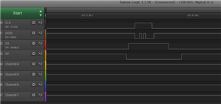
Thanks in advance.
Regards,
Kalyan

Parents
  • Thanks for this example Edvin. I was in the process of trying to get an ADXL372 in spi mode going with an nRF52840 dev kit.

    I have not been able to get the chip select working (nrfx_spi.c if p_config->ss_pin set to 0xFF NRFX_SPI_PIN_NOT_USED).  So it appears the work around in the sample you showed of using gpio_pin_set() at the main.c level was the only way I good send valid mosi data. The only change would be that I did not OR the SPI_MODE_CP0L bit so the clock goes back low.

    I am using nrf connect sdk and building with SES 1.4.99 dev1. I am running the adxl372 sample using this in the overlay. I can get your sample working with the same overlay and prj.config, but when I run the adxl372 example I get no activity on the logic analyzer.

    My question is would a sensor driver need to call gpio_pin_set() for the ss pin to function?

    &spi1 {
    cs-gpios = <&gpio0 16 GPIO_ACTIVE_LOW>;
    sck-pin = <31>;
    mosi-pin = <30>;
    miso-pin = <40>;
    adxl372@0 {
    compatible = "adi,adxl372";
    reg = <0>;
    spi-max-frequency = <1000000>;
    //spi-max-frequency = <8000000>;
    label = "ADXL372";
    int1-gpios = <&gpio1 14 GPIO_ACTIVE_HIGH>;
    };
    };
    &spi2 {
    status = "disabled";
    };

    &gpiote {
    status = "okay";
    };

    &gpio0 {
    status = "okay";
    };

    &gpio1 {
    status = "okay";
    };

    prj.conf

    CONFIG_STDOUT_CONSOLE=y
    CONFIG_LOG=y

    CONFIG_GPIO=y
    CONFIG_SPI=y
    CONFIG_SPI_1=y
    CONFIG_SPI_2=n
    CONFIG_SPI_NRFX=y
    CONFIG_SENSOR=y
    CONFIG_ADXL372=y
    CONFIG_ADXL372_SPI=y
    CONFIG_SENSOR_LOG_LEVEL_WRN=y

    CONFIG_CBPRINTF_FP_SUPPORT=y

Reply
  • Thanks for this example Edvin. I was in the process of trying to get an ADXL372 in spi mode going with an nRF52840 dev kit.

    I have not been able to get the chip select working (nrfx_spi.c if p_config->ss_pin set to 0xFF NRFX_SPI_PIN_NOT_USED).  So it appears the work around in the sample you showed of using gpio_pin_set() at the main.c level was the only way I good send valid mosi data. The only change would be that I did not OR the SPI_MODE_CP0L bit so the clock goes back low.

    I am using nrf connect sdk and building with SES 1.4.99 dev1. I am running the adxl372 sample using this in the overlay. I can get your sample working with the same overlay and prj.config, but when I run the adxl372 example I get no activity on the logic analyzer.

    My question is would a sensor driver need to call gpio_pin_set() for the ss pin to function?

    &spi1 {
    cs-gpios = <&gpio0 16 GPIO_ACTIVE_LOW>;
    sck-pin = <31>;
    mosi-pin = <30>;
    miso-pin = <40>;
    adxl372@0 {
    compatible = "adi,adxl372";
    reg = <0>;
    spi-max-frequency = <1000000>;
    //spi-max-frequency = <8000000>;
    label = "ADXL372";
    int1-gpios = <&gpio1 14 GPIO_ACTIVE_HIGH>;
    };
    };
    &spi2 {
    status = "disabled";
    };

    &gpiote {
    status = "okay";
    };

    &gpio0 {
    status = "okay";
    };

    &gpio1 {
    status = "okay";
    };

    prj.conf

    CONFIG_STDOUT_CONSOLE=y
    CONFIG_LOG=y

    CONFIG_GPIO=y
    CONFIG_SPI=y
    CONFIG_SPI_1=y
    CONFIG_SPI_2=n
    CONFIG_SPI_NRFX=y
    CONFIG_SENSOR=y
    CONFIG_ADXL372=y
    CONFIG_ADXL372_SPI=y
    CONFIG_SENSOR_LOG_LEVEL_WRN=y

    CONFIG_CBPRINTF_FP_SUPPORT=y

Children
No Data
Related