
Hello, guys!
We started designing our custom nRF9160 SiP based board. We currently feel that the most challenging would be to design the part around LTE/GPS RF networks. In that sense, I made a comparison between nRF9160-DK Hardware files (version 0.10.2) and Thingy:91 Hardware files (version 1.4.0).
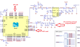
nRF9160-DK design approach:
RF part on nRF9160-DK board seems to be simpler and cheaper to implement. COEX0 pin of nRF9160 is used to disable GPS part when LTE modem is active. MAGPIOs are not used. Two separate ports of the P822601 antenna are used for LTE and GPS. Finally, there is only one matching network for LTE RF signal.
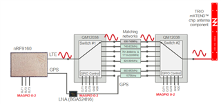
Thingy:91 approach:
On the other hand, Thingy:91 is using QM1238 SP8T switches and MAGPIO0-2 pins of nRF9160 SiP to fine-tune the frequency band. Only one port of NN03-310 antenna is used for both LTE and GPS. COEX0 GPIO of nRF9160 is used to let nRF52840 SoC know that the LTE modem is active. This approach seems to be more expensive and more complex to implement. There is a great webinar that explains the design process though (link).
I would like to ask the following questions:
- Which Frequency band is covered with the LTE matching network on nRF9160-DK board?
- What are the benefits of using Thingy:91 approach, do we get global coverage with a single design together with the increased efficiency?
- In Thingy:91 approach, if we select only bands B8 and B20, for example, will MAGPIOs automatically adapt to the desired bands selecting only appropriate matching networks on the board or they are gonna continuously run 000, 001, 010, 011, 100, 101, 110, 111 patterns?
Thanks in advance for your time and efforts.
Sincerely,
Bojan.

