This post is older than 2 years and might not be relevant anymore
More Info: Consider searching for newer posts

Generated arbitrary wave with PWM controller

Is there a way to generate a square wave like the one in the picture without using any kind of interruption to change settings middle-wave?


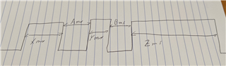
For example, the wave can be 50ms on, 25 ms off, 50ms on, 25ms off, 150ms on, and then the sequence is over

I'm reading the doc on the PWM controller, but I'm not sure how to do something like that. How can I set the different periods (the 50, 25, and 150 ms)?

The base requirement here is that I can just start the sequence and then just handle an event when it finishes, but I can't use the CPU to handle the level changes

Thank you so much!

Parents
  • I'm reading the doc on the PWM controller, but I'm not sure how to do something like that. How can I set the different periods (the 50, 25, and 150 ms)?

     I suggest you read the PWM driver documentation and PWM driver API documentation, and then go through the PWM Driver Example in order to familiarize yourself with the PWM peripheral. 

    You'll need to use the arbitrary waveform generator, it sounds fanzy, but it's actually fairly simple to use. Include the given COUNTERTOP value in the given Sequence as shown in figure 4 in Decoder with EasyDMA

    The idea is to break down your signal into sequences of PWM periods, where each Sequence sample is one PWM period. In this case X + A, Y + B, and Z + "Zend" are each a full PWM period with countertop values of X + A, Y + B, Z+Zend, and compare values of X, Y, and Z respectively.
    In this case Zend is an imagined construct to fit the last pulse to a PWM period. If you set countertop = Z and Zend=0 you'll get a PWM period of length Z and 100% duty-cycle.

Reply
  • I'm reading the doc on the PWM controller, but I'm not sure how to do something like that. How can I set the different periods (the 50, 25, and 150 ms)?

     I suggest you read the PWM driver documentation and PWM driver API documentation, and then go through the PWM Driver Example in order to familiarize yourself with the PWM peripheral. 

    You'll need to use the arbitrary waveform generator, it sounds fanzy, but it's actually fairly simple to use. Include the given COUNTERTOP value in the given Sequence as shown in figure 4 in Decoder with EasyDMA

    The idea is to break down your signal into sequences of PWM periods, where each Sequence sample is one PWM period. In this case X + A, Y + B, and Z + "Zend" are each a full PWM period with countertop values of X + A, Y + B, Z+Zend, and compare values of X, Y, and Z respectively.
    In this case Zend is an imagined construct to fit the last pulse to a PWM period. If you set countertop = Z and Zend=0 you'll get a PWM period of length Z and 100% duty-cycle.

Children
Related