
Hi!
I wanted to ask someone who knows more than I, if this setup makes sense, and how I could test my design.
A bit of background: We're developing a custom board which works with an nRF52840 chipset and has some peripherals onboard which server some function. I wanted to test current consumption on my board so I started with an input DC power supply, set the current max and set the voltage to ~3.0V to simulate a CR2032 battery. I ran the test and got the results.
Now, I want to test with an actual CR2032 battery, so I replaced the DC power supply with a CR2032 and got the setup described below.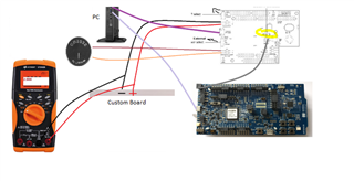
Now my problem is that my device would either not start at all, or start and shut down after a very very short amount of time (seconds), due to low voltage. This happens with all batteries (even new ones) and the voltage measured on the battery after I take it out reads very low ~2.something V. This repeats whether I have the DMM connected in parallel or not.
So, I'm assuming there is a huge peak in current consumption which leads to a large drop in battery voltage. The DC supply can handle this, but the battery can not, and so my device shuts down. I'm also assuming the PPK itself - which is connected in series with my DUT, has some voltage drop on it, so my DUT isn't getting the full voltage from the battery.
my questions are:
1. Is my analysis of the cause of the failed measurement reasonable?
2. What is the usual way by which one measures power consumption with devices such as this? Is a DC power supply a reasonable simulation of the behavior of the device with a CR2032 battery?
3. Is a set of measurements with the PPK with a CR2032 battery as input possible? if so, is there a 'proper' way to set this up?
Thanks!
