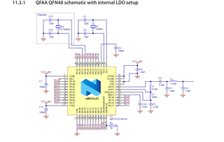
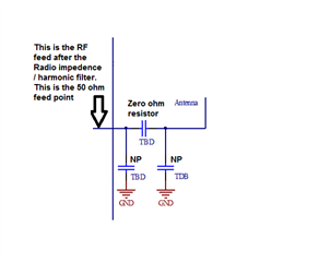
1) It converts the balanced differential output to a single ended unbalanced 5o ohm feed point.
2) It acts as a low pass filter, filtering out harmonics.
3) The VDD_PA pin goes high 50us before the radio starts to transmit. This voltage goes thru L1 and back into the part on ANT1 and ANT2. This feeds the internal transmitter power amplifiers. C5, not only is part of the matching network but also acts as a DC blocking cap.
Note that the VDD_PA line does not have much in the way of driving capabilities.
You will still need to have a matching network for your antenna. We suggest starting with a PI network and then the number of components and values can be determined at time of tuning and testing.
If I may, I would suggest that you take a look at one of our newer nRF52 series parts. They are BT 5.x compliant. They are faster, more then half the current consumption. Depending on the nRF52 variant they also have a 4dBm or 8dBm power output capability And they are supported with free new IDE tools from Segger. Just a suggestion.