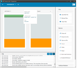
When I program the Zigbee cli example from T&Z SDK v4.1.0 I see that the Zigbee stack uses some flash areas at the end of the chip. In my case 304 bytes @ 0x000F7000 and 24 bytes @ 0x000FB000. I would like to change the location of these two areas, because I need these areas for the bootloader. I don’t see where these areas are defined. Can you tell me if and where it is possible to change them?