This post is older than 2 years and might not be relevant anymore
More Info: Consider searching for newer posts

The characters that are output by J-link's virtual port are broken.

Hello

I'm going to use J-link's virtual port to see the characters being printed.

I connected custom pcb to Vcc, Swdio, Swclk, Gnd pin and tx, rx pin of J-link.

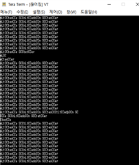
And I opened the port in the serial terminal and checked it, and as shown in the picture below, the data are broken and printed out.


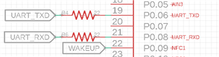
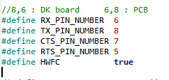
The circuit diagram has tx, rx connected to the 6 and 8 pins.


Can you tell me why the data is broken in the serial terminal like this?

Thank you.

  • Hi.

    Hard to say what is causing this.

    Maybe you could add some more data on how you are sending data, connecting to the device, what kind of device you are using (on both sides), SDK version etc.

    Br,
    Joakim

  • Hi, Joakim.

    I use nrf52832 and J-link EDU and sdk v17.0.
    I am testing with UART example for a test. I revised the code of pca10040.h and could this be a problem?

    #ifndef PCA10040_H
    #define PCA10040_H
    
    #ifdef __cplusplus
    extern "C" {
    #endif
    
    #include "nrf_gpio.h"
    
    #define LEDS_NUMBER    5
    
    #define LED_START      16
    #define LED_1          17
    #define LED_2          19 //Pairing LED
    #define LED_6          16 //LED 6~10 : BAT_LED 
    #define LED_7          18
    #define LED_8          20
    #define LED_9          30
    #define LED_10         31
    #define LED_STOP       31
    
    #define LEDS_ACTIVE_STATE 0
    
    #define LEDS_INV_MASK  LEDS_MASK
    
    //#define LEDS_LIST { LED_1, LED_2, LED_3, LED_4 }
    #define LEDS_LIST {BAT_LED_1, BAT_LED_2, BAT_LED_3, BAT_LED_4, BAT_LED_5} //PCB LED
    #define LEDS_LIST2 {BAT_LED_3, BAT_LED_2, BAT_LED_1, BAT_LED_4} //Left move LED
    #define LEDS_LIST3 {BAT_LED_1, BAT_LED_2, BAT_LED_3, BAT_LED_5} //Right move LED 
    
    #define BSP_LED_0      LED_1
    #define BSP_LED_1      LED_2
    #define BSP_LED_2      LED_3
    #define BSP_LED_3      LED_4
    #define BSP_LED_4      LED_5
    
    #define BUTTONS_NUMBER 1
    //#define BUTTONS_NUMBER 4
    
    #define BUTTON_START   28
    #define BUTTON_1       28
    //#define BUTTON_2       14
    //#define BUTTON_3       15
    //#define BUTTON_4       16
    #define BUTTON_STOP    28
    #define BUTTON_PULL    NRF_GPIO_PIN_PULLUP
    
    #define BUTTONS_ACTIVE_STATE 0
    
    #define BUTTONS_LIST { BUTTON_1}
    
    #define BSP_BUTTON_0   BUTTON_1
    
    //8,6 : DK board     6,8 : PCB
    #define RX_PIN_NUMBER  6
    #define TX_PIN_NUMBER  8 
    #define CTS_PIN_NUMBER 7
    #define RTS_PIN_NUMBER 5
    #define HWFC           true
    
    /*#define SPIS_MISO_PIN   28  // SPI MISO signal.
    #define SPIS_CSN_PIN    12  // SPI CSN signal.
    #define SPIS_MOSI_PIN   25  // SPI MOSI signal.
    #define SPIS_SCK_PIN    29  // SPI SCK signal.
    
    #define SPIM0_SCK_PIN   29  // SPI clock GPIO pin number.
    #define SPIM0_MOSI_PIN  25  // SPI Master Out Slave In GPIO pin number.
    #define SPIM0_MISO_PIN  28  // SPI Master In Slave Out GPIO pin number.
    #define SPIM0_SS_PIN    12  // SPI Slave Select GPIO pin number.
    
    #define SPIM1_SCK_PIN   2   // SPI clock GPIO pin number.
    #define SPIM1_MOSI_PIN  3   // SPI Master Out Slave In GPIO pin number.
    #define SPIM1_MISO_PIN  4   // SPI Master In Slave Out GPIO pin number.
    #define SPIM1_SS_PIN    5   // SPI Slave Select GPIO pin number.
    
    #define SPIM2_SCK_PIN   12  // SPI clock GPIO pin number.
    #define SPIM2_MOSI_PIN  13  // SPI Master Out Slave In GPIO pin number.
    #define SPIM2_MISO_PIN  14  // SPI Master In Slave Out GPIO pin number.
    #define SPIM2_SS_PIN    15  // SPI Slave Select GPIO pin number.
    
    // serialization APPLICATION board - temp. setup for running serialized MEMU tests
    #define SER_APP_RX_PIN              23    // UART RX pin number.
    #define SER_APP_TX_PIN              24    // UART TX pin number.
    #define SER_APP_CTS_PIN             2     // UART Clear To Send pin number.
    #define SER_APP_RTS_PIN             25    // UART Request To Send pin number.
    
    #define SER_APP_SPIM0_SCK_PIN       12     // SPI clock GPIO pin number.
    #define SER_APP_SPIM0_MOSI_PIN      13      // SPI Master Out Slave In GPIO pin number
    #define SER_APP_SPIM0_MISO_PIN      14     // SPI Master In Slave Out GPIO pin number
    #define SER_APP_SPIM0_SS_PIN        23     // SPI Slave Select GPIO pin number
    #define SER_APP_SPIM0_RDY_PIN       25     // SPI READY GPIO pin number
    #define SER_APP_SPIM0_REQ_PIN       24     // SPI REQUEST GPIO pin number
    
    // serialization CONNECTIVITY board
    #define SER_CON_RX_PIN              24    // UART RX pin number.
    #define SER_CON_TX_PIN              23    // UART TX pin number.
    #define SER_CON_CTS_PIN             25    // UART Clear To Send pin number. Not used if HWFC is set to false.
    #define SER_CON_RTS_PIN             2     // UART Request To Send pin number. Not used if HWFC is set to false.
    
    
    #define SER_CON_SPIS_SCK_PIN        27    // SPI SCK signal.
    #define SER_CON_SPIS_MOSI_PIN       2     // SPI MOSI signal.
    #define SER_CON_SPIS_MISO_PIN       26    // SPI MISO signal.
    #define SER_CON_SPIS_CSN_PIN        23    // SPI CSN signal.
    #define SER_CON_SPIS_RDY_PIN        25    // SPI READY GPIO pin number.
    #define SER_CON_SPIS_REQ_PIN        24    // SPI REQUEST GPIO pin number.  */
    
    #define SER_CONN_CHIP_RESET_PIN     21 //11    // Pin used to reset connectivity chip
    
    
    // Arduino board mappings
    #define ARDUINO_SCL_PIN             27     // SCL signal pin
    #define ARDUINO_SDA_PIN             26     // SDA signal pin
    #define ARDUINO_AREF_PIN            2     // Aref pin
    /*#define ARDUINO_13_PIN              25    // Digital pin 13
    #define ARDUINO_12_PIN              24    // Digital pin 12
    #define ARDUINO_11_PIN              23    // Digital pin 11
    #define ARDUINO_10_PIN              22    // Digital pin 10
    #define ARDUINO_9_PIN               20    // Digital pin 9
    #define ARDUINO_8_PIN               19    // Digital pin 8
    
    #define ARDUINO_7_PIN               18    // Digital pin 7
    #define ARDUINO_6_PIN               17    // Digital pin 6
    #define ARDUINO_5_PIN               16    // Digital pin 5
    #define ARDUINO_4_PIN               15    // Digital pin 4
    #define ARDUINO_3_PIN               14    // Digital pin 3
    #define ARDUINO_2_PIN               13    // Digital pin 2
    #define ARDUINO_1_PIN               12    // Digital pin 1
    #define ARDUINO_0_PIN               11    // Digital pin 0
    
    #define ARDUINO_A0_PIN              2     // Analog channel 0
    #define ARDUINO_A1_PIN              3     // Analog channel 1
    #define ARDUINO_A2_PIN              4    // Analog channel 2
    #define ARDUINO_A3_PIN              5    // Analog channel 3
    #define ARDUINO_A4_PIN              28    // Analog channel 4
    #define ARDUINO_A5_PIN              29    // Analog channel 5
    #define ARDUINO_A6_PIN              30    // Analog channel 6
    #define ARDUINO_A7_PIN              31    // Analog channel 7
    */
    
    #define APP_BTN_1 	28 //POWER_STATE pin
    //#define BAT_ADC		3 //A0
    #define BUZZER_PIN 	25
    
    #define BAT_LED_1   16 
    #define BAT_LED_2   18 
    #define BAT_LED_3   20 
    #define BAT_LED_4   30 
    #define BAT_LED_5   31 
    
    #define Pairing_LED  19
    
    #define POWER_SW  29 //POWER_HOLD pin
    
    #define bat_state  22 //battery charge state(CHG)
    
    
    #ifdef __cplusplus
    }
    #endif
    
    #endif // PCA10040_H

    Thank you.

  • I can't see any problems with that.

    Are you sure that your application doesn't use the same pins as the uart for anything else that might brake the data?

    Also, if the pins are left floating this might happen, but it doesn't seem like that could be the issue?

    Br

  • There have been many problems with the custom PCB that I'm testing. (There are some problems, such as turning off the power just by the microcurrent of the hand.)

    I think this problem might be a hardware problem. I will check it again and test it.


    Thank you.

  • Ok, thank you for letting me know.

    Let me know if there is someting else I can help you with!

    Br,
    Joakim

Related