Hello,
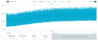
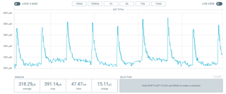
I'm using zephyr to develop a battery powered IoT device with a sensor and a LoRa transceiver (SX126x). And I'm expecting to achieve average consumption values (during "sleep" mode) around ~15uA. At this moment I can only get ~360uA. I've already found many other users with the same issue in this forum and already know that I need to deactivate the SoC's peripherals that I'm not using. The issue is that I can't find which peripherals are these, already tried to deactivate some but the results were not the expected. To ease my debug processes, I developed a small code with a similar behavior as the one to be used in the final product, which I will share here:
#include <zephyr.h>
#include <sys/printk.h>
#include <power/power.h>
#include <device.h>
#include <drivers/i2c.h>
#include <drivers/spi.h>
#include <drivers/lora.h>
#include <drivers/counter.h>
#include <radio.h>

#define I2C_DEV DT_INST(0, nordic_nrf_twi)

#define DEFAULT_RADIO_NODE DT_ALIAS(lora0)
BUILD_ASSERT(DT_NODE_HAS_STATUS(DEFAULT_RADIO_NODE, okay),
	     "No default LoRa radio specified in DT");
#define DEFAULT_RADIO DT_LABEL(DEFAULT_RADIO_NODE)

#if defined(CONFIG_COUNTER_RTC0)
#define TIMER DT_LABEL(DT_NODELABEL(rtc0))
#elif defined(CONFIG_COUNTER_RTC1)
#define TIMER DT_LABEL(DT_NODELABEL(rtc1))
#elif defined(CONFIG_COUNTER_RTC2)
#define TIMER DT_LABEL(DT_NODELABEL(rtc2))
#endif

#define CONSOLE_LABEL DT_LABEL(DT_CHOSEN(zephyr_console))

#define MAX_DATA_LEN 10

void t1_f();
void alarm_cback(struct device *counter_dev, uint8_t chan_id, uint32_t ticks, void *user_data);
void wakeup();
void sleep();

struct device *i2c_dev, *lora_dev, *counter, *cons;
struct counter_alarm_cfg alarm;
struct lora_modem_config lora;
char data[MAX_DATA_LEN] = {'h', 'e', 'l', 'l', 'o', 'w', 'o', 'r', 'l', 'd'};

K_THREAD_DEFINE(t1, 1024, t1_f, NULL, NULL, NULL, -1, 0, 0);

void main(void)
{
    cons = device_get_binding(CONSOLE_LABEL);
    printk("Initializing test...\n");
	i2c_dev = device_get_binding(DT_LABEL(I2C_DEV));
	if (!i2c_dev) {
		printk("I2C: Device driver not found.\n");
		return;
	}
	lora_dev = device_get_binding(DEFAULT_RADIO);
	if (!lora_dev) {
		printk("LORA: Device driver not found.\n");
		return;
	}
	lora.frequency = 868100000;
	lora.bandwidth = BW_125_KHZ;
	lora.datarate = SF_10;
	lora.preamble_len = 8;
	lora.coding_rate = CR_4_5;
	lora.tx_power = 4;
	lora.tx = true;
	lora_config(lora_dev, &lora);
    counter = device_get_binding(TIMER);
    if (!counter) {
		printk("COUNTER: Device driver not found.\n");
		return;
    }
    counter_start(counter);
    alarm.flags = 0;
    alarm.ticks = counter_us_to_ticks(counter, 10000000);
    alarm.callback = alarm_cback;
    counter_set_channel_alarm(counter, 0, &alarm);
    sleep();
}

void t1_f(void){
	int ret;
    uint8_t buffer[2];
    while (true)
    {
        k_sleep(K_FOREVER);
        wakeup();
        printk("t1\n");
        i2c_reg_read_byte(i2c_dev, 0x41, 0xFF, &buffer[0]); //0x07
        i2c_reg_read_byte(i2c_dev, 0x41, 0xFE, &buffer[1]); //0xD0
        printk("DEVID: %02x%02x\n", buffer[0], buffer[1]);
        ret = lora_send(lora_dev, data, MAX_DATA_LEN);
		if (ret < 0) {
			printk("LoRa send failed\n");
			return;
		}
		printk("Data sent!\n");
        k_busy_wait(3000000);
        sleep();
    }
}

void alarm_cback(struct device *counter_dev, uint8_t chan_id, uint32_t ticks, void *user_data){
    k_wakeup(t1);
    counter_set_channel_alarm(counter, 0, &alarm);
}

void wakeup(){
    device_set_power_state(cons, DEVICE_PM_ACTIVE_STATE, NULL, NULL);
    device_set_power_state(i2c_dev, DEVICE_PM_ACTIVE_STATE, NULL, NULL);
    device_set_power_state(lora_dev, DEVICE_PM_ACTIVE_STATE, NULL, NULL);
}

void sleep(){
    device_set_power_state(cons, DEVICE_PM_OFF_STATE, NULL, NULL);
    device_set_power_state(i2c_dev, DEVICE_PM_OFF_STATE, NULL, NULL);
    device_set_power_state(lora_dev, DEVICE_PM_OFF_STATE, NULL, NULL);
}
CONFIG_CONSOLE=y
CONFIG_I2C=y
CONFIG_SPI=y
CONFIG_GPIO=y
CONFIG_PRINTK=y

CONFIG_COUNTER=y
CONFIG_COUNTER_RTC0=y

CONFIG_LORA=y
CONFIG_LORA_SX12XX=y
CONFIG_LORA_SX126X=y

CONFIG_SYS_POWER_MANAGEMENT=y
CONFIG_TICKLESS_IDLE=y
CONFIG_DEVICE_POWER_MANAGEMENT=y
I could summarize my questions in:
- Is there a better form of managing the devices in Zephyr?
- Is there a way to know which devices are being used, and in which mode are they?
- Or if I'm thinking right, but doing something wrong in the code?
Kind regards,
Diogo Correia
PS: these values were measured using the power profile kit in external mode due to the presence of a shield in the development board.