This post is older than 2 years and might not be relevant anymore
More Info: Consider searching for newer posts

Low power mode in Zephyr

Hello,

I'm using zephyr to develop a battery powered IoT device with a sensor and a LoRa transceiver (SX126x). And I'm expecting to achieve average consumption values (during "sleep" mode) around ~15uA. At this moment I can only get ~360uA. I've already found many other users with the same issue in this forum and already know that I need to deactivate the SoC's peripherals that I'm not using. The issue is that I can't find which peripherals are these, already tried to deactivate some but the results were not the expected. To ease my debug processes, I developed a small code with a similar behavior as the one to be used in the final product, which I will share here:

#include <zephyr.h>
#include <sys/printk.h>
#include <power/power.h>
#include <device.h>
#include <drivers/i2c.h>
#include <drivers/spi.h>
#include <drivers/lora.h>
#include <drivers/counter.h>
#include <radio.h>

#define I2C_DEV DT_INST(0, nordic_nrf_twi)

#define DEFAULT_RADIO_NODE DT_ALIAS(lora0)
BUILD_ASSERT(DT_NODE_HAS_STATUS(DEFAULT_RADIO_NODE, okay),
	     "No default LoRa radio specified in DT");
#define DEFAULT_RADIO DT_LABEL(DEFAULT_RADIO_NODE)

#if defined(CONFIG_COUNTER_RTC0)
#define TIMER DT_LABEL(DT_NODELABEL(rtc0))
#elif defined(CONFIG_COUNTER_RTC1)
#define TIMER DT_LABEL(DT_NODELABEL(rtc1))
#elif defined(CONFIG_COUNTER_RTC2)
#define TIMER DT_LABEL(DT_NODELABEL(rtc2))
#endif

#define CONSOLE_LABEL DT_LABEL(DT_CHOSEN(zephyr_console))

#define MAX_DATA_LEN 10

void t1_f();
void alarm_cback(struct device *counter_dev, uint8_t chan_id, uint32_t ticks, void *user_data);
void wakeup();
void sleep();

struct device *i2c_dev, *lora_dev, *counter, *cons;
struct counter_alarm_cfg alarm;
struct lora_modem_config lora;
char data[MAX_DATA_LEN] = {'h', 'e', 'l', 'l', 'o', 'w', 'o', 'r', 'l', 'd'};

K_THREAD_DEFINE(t1, 1024, t1_f, NULL, NULL, NULL, -1, 0, 0);

void main(void)
{
    cons = device_get_binding(CONSOLE_LABEL);
    printk("Initializing test...\n");
	i2c_dev = device_get_binding(DT_LABEL(I2C_DEV));
	if (!i2c_dev) {
		printk("I2C: Device driver not found.\n");
		return;
	}
	lora_dev = device_get_binding(DEFAULT_RADIO);
	if (!lora_dev) {
		printk("LORA: Device driver not found.\n");
		return;
	}
	lora.frequency = 868100000;
	lora.bandwidth = BW_125_KHZ;
	lora.datarate = SF_10;
	lora.preamble_len = 8;
	lora.coding_rate = CR_4_5;
	lora.tx_power = 4;
	lora.tx = true;
	lora_config(lora_dev, &lora);
    counter = device_get_binding(TIMER);
    if (!counter) {
		printk("COUNTER: Device driver not found.\n");
		return;        
    }
    counter_start(counter);
    alarm.flags = 0;
    alarm.ticks = counter_us_to_ticks(counter, 10000000);
    alarm.callback = alarm_cback;
    counter_set_channel_alarm(counter, 0, &alarm);
    sleep();
}

void t1_f(void){
	int ret;    
    uint8_t buffer[2];
    while (true)
    {
        k_sleep(K_FOREVER);
        wakeup();
        printk("t1\n");
        i2c_reg_read_byte(i2c_dev, 0x41, 0xFF, &buffer[0]); //0x07
        i2c_reg_read_byte(i2c_dev, 0x41, 0xFE, &buffer[1]); //0xD0
        printk("DEVID: %02x%02x\n", buffer[0], buffer[1]);
        ret = lora_send(lora_dev, data, MAX_DATA_LEN);
		if (ret < 0) {
			printk("LoRa send failed\n");
			return;
		}
		printk("Data sent!\n");
        k_busy_wait(3000000);
        sleep();
    }
}

void alarm_cback(struct device *counter_dev, uint8_t chan_id, uint32_t ticks, void *user_data){
    k_wakeup(t1);
    counter_set_channel_alarm(counter, 0, &alarm);
}

void wakeup(){
    device_set_power_state(cons, DEVICE_PM_ACTIVE_STATE, NULL, NULL);
    device_set_power_state(i2c_dev, DEVICE_PM_ACTIVE_STATE, NULL, NULL);
    device_set_power_state(lora_dev, DEVICE_PM_ACTIVE_STATE, NULL, NULL);
}

void sleep(){
    device_set_power_state(cons, DEVICE_PM_OFF_STATE, NULL, NULL);
    device_set_power_state(i2c_dev, DEVICE_PM_OFF_STATE, NULL, NULL);
    device_set_power_state(lora_dev, DEVICE_PM_OFF_STATE, NULL, NULL);
}

CONFIG_CONSOLE=y
CONFIG_I2C=y
CONFIG_SPI=y
CONFIG_GPIO=y
CONFIG_PRINTK=y

CONFIG_COUNTER=y
CONFIG_COUNTER_RTC0=y

CONFIG_LORA=y
CONFIG_LORA_SX12XX=y
CONFIG_LORA_SX126X=y

CONFIG_SYS_POWER_MANAGEMENT=y
CONFIG_TICKLESS_IDLE=y
CONFIG_DEVICE_POWER_MANAGEMENT=y

I could summarize my questions in:

  • Is there a better form of managing the devices in Zephyr?
  • Is there a way to know which devices are being used, and in which mode are they?
  • Or if I'm thinking right, but doing something wrong in the code?

Kind regards,

Diogo Correia

PS: these values were measured using the power profile kit in external mode due to the presence of a shield in the development board.

Parents
  • Hi, are you using nRF52840? I have a feeling that the extra current is a result of UART1 being turned on. All UART instances are turned on by default in Zephyr.

    Create a file called nrf52840dk_nrf52840.overlay in the project root folder and add this:

    &uart1 {
        status = "disabled";
    };

    Unfortunately there's no easy way to see which devices are turned on in zephyr. Other than that I think your code looks good. The way you turn off logging (and hence UART0) looks fine:

    device_set_power_state(cons, DEVICE_PM_OFF_STATE, NULL, NULL);


    PS: these values were measured using the power profile kit in external mode due to the presence of a shield in the development board.
     How do you connect the PPK? If you are measuring on a nRF52 DK and power the DK thorugh the external supply header, the idle current is expected to be high because you power the debugger chip as well.

  • Having no success with my modifications on the driver. Tried to use the same method (device_set_power_state) with all GPIOs and the SPI device driver. When deactivating the first, nothing special appears to happen on the consumption. When I deactivate SPI, the consumption increases in the order of mA (guess is something related with the context loss that is described in zephyr documentation). Do you have any suggestion in how to address this issue? Or is it better to ask in zephy's mailing list?

    Device Driver structure:

    struct sx126x_data {
    	const struct device *reset;
    	const struct device *busy;
    	const struct device *dio1;
    	struct gpio_callback dio1_irq_callback;
    	struct k_work dio1_irq_work;
    	DioIrqHandler *radio_dio_irq;
    #if HAVE_GPIO_ANTENNA_ENABLE
    	const struct device *antenna_enable;
    #endif
    #if HAVE_GPIO_TX_ENABLE
    	const struct device *tx_enable;
    #endif
    #if HAVE_GPIO_RX_ENABLE
    	const struct device *rx_enable;
    #endif
    	const struct device *spi;
    	struct spi_config spi_cfg;
    #if HAVE_GPIO_CS
    	struct spi_cs_control spi_cs;
    #endif
    	RadioOperatingModes_t mode;
    #ifdef CONFIG_DEVICE_POWER_MANAGEMENT
    	uint32_t pm_state;
    #endif
    } dev_data;

    My PM function:

    #ifdef CONFIG_DEVICE_POWER_MANAGEMENT
    
    static int sx126x_lora_pm_control(const struct device *dev, uint32_t ctrl_command,
    				 void *context, device_pm_cb cb, void *arg)
    {
    	int ret = 0;
    	struct sx126x_data *data = (struct sx126x_data *)dev->data;
    
    	switch (ctrl_command) {
    	case DEVICE_PM_SET_POWER_STATE:
    		if (*((uint32_t *)context) == DEVICE_PM_ACTIVE_STATE) {
    			data->pm_state = DEVICE_PM_ACTIVE_STATE;
    			device_set_power_state(data->reset, DEVICE_PM_ACTIVE_STATE, NULL, NULL);
    			device_set_power_state(data->busy, DEVICE_PM_ACTIVE_STATE, NULL, NULL);
    			device_set_power_state(data->dio1, DEVICE_PM_ACTIVE_STATE, NULL, NULL);
    			#if HAVE_GPIO_ANTENNA_ENABLE
    				device_set_power_state(data->antenna_enable, DEVICE_PM_ACTIVE_STATE, NULL, NULL);
    			#endif
    			#if HAVE_GPIO_TX_ENABLE
    				device_set_power_state(data->tx_enable, DEVICE_PM_ACTIVE_STATE, NULL, NULL);
    			#endif
    			#if HAVE_GPIO_RX_ENABLE
    				device_set_power_state(data->rx_enable, DEVICE_PM_ACTIVE_STATE, NULL, NULL);
    			#endif
    		} else {
    			data->pm_state = DEVICE_PM_OFF_STATE;
    			device_set_power_state(data->reset, DEVICE_PM_OFF_STATE, NULL, NULL);
    			device_set_power_state(data->busy, DEVICE_PM_OFF_STATE, NULL, NULL);
    			device_set_power_state(data->dio1, DEVICE_PM_OFF_STATE, NULL, NULL);
    			#if HAVE_GPIO_ANTENNA_ENABLE
    				device_set_power_state(data->antenna_enable, DEVICE_PM_OFF_STATE, NULL, NULL);
    			#endif
    			#if HAVE_GPIO_TX_ENABLE
    				device_set_power_state(data->tx_enable, DEVICE_PM_OFF_STATE, NULL, NULL);
    			#endif
    			#if HAVE_GPIO_RX_ENABLE
    				device_set_power_state(data->rx_enable, DEVICE_PM_OFF_STATE, NULL, NULL);
    			#endif
    			ret = 0;
    		}
    		break;
    	case DEVICE_PM_GET_POWER_STATE:
    		*((uint32_t *)context) = data->pm_state;
    		break;
    	default:
    		ret = -EINVAL;
    	}
    
    	if (cb != NULL) {
    		cb(dev, ret, context, arg);
    	}
    	return ret;
    }
    #endif /* CONFIG_DEVICE_POWER_MANAGEMENT */
    
    #ifndef CONFIG_DEVICE_POWER_MANAGEMENT
    DEVICE_AND_API_INIT(sx126x_lora, DT_INST_LABEL(0),
    		    &sx126x_lora_init, NULL,
    		    NULL, POST_KERNEL, CONFIG_LORA_INIT_PRIORITY,
    		    &sx126x_lora_api);
    #else
    DEVICE_DEFINE(sx126x_lora, DT_INST_LABEL(0), &sx126x_lora_init,
    	      sx126x_lora_pm_control, &dev_data, NULL, POST_KERNEL,
    	      CONFIG_LORA_INIT_PRIORITY, &sx126x_lora_api);
    #endif /* CONFIG_DEVICE_POWER_MANAGEMENT */

  • Hi, sorry for not getting back to you, I missed your last reply. Were you able to figure out this? Did you get any help from the Zephyr mailing list?

  • Hi, Stian. No, I haven't figured out how to solve this issue. Any idea?

  • Hi, I'm not familiar with the SX126x driver, so I think we first need to figure out which peripherals are active. As I  understand the communication protocol is SPI? The SPI should not consume any significant current unless it's actively transmitting. Any other peripherals being used?

    Also the current consumption could be due to some polling feature in the LoRa driver. I recently had a case where a WiFi module driver was configured with a 1ms polling timer, which lead to a current consumption of 490 uA.

    If you are able to plot the current consumption you should be able to see if there are any timers waking up the CPU regularly (be aware that there will be spikes due to DCDC switching, but they should be distinguishable from the wakeup timers).

Reply
  • Hi, I'm not familiar with the SX126x driver, so I think we first need to figure out which peripherals are active. As I  understand the communication protocol is SPI? The SPI should not consume any significant current unless it's actively transmitting. Any other peripherals being used?

    Also the current consumption could be due to some polling feature in the LoRa driver. I recently had a case where a WiFi module driver was configured with a 1ms polling timer, which lead to a current consumption of 490 uA.

    If you are able to plot the current consumption you should be able to see if there are any timers waking up the CPU regularly (be aware that there will be spikes due to DCDC switching, but they should be distinguishable from the wakeup timers).

Children
  • From my reading of the driver code, beside the SPI peripheral, the driver uses five GPIO pins: ANTENNA_ENABLE, TX_ENABLE, RX_ENABLE, RESET and DIO1. The first four pins are output pins, and are grounded during sleep. And the latter is an input pin, used by the LoRa board for callback.

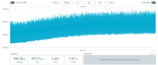
    Here are the plots with the device's current consumption, during sleep mode. The first plot shows the current consumption along all the sleep mode time. And, the second plot, is a zoomed view of the first one.

  • It looks like you have some leakage on the VDD domain since the base current between the spikes is so high. The varying current could be a floating GPIO input.

    I think we should first try to verify the measurement setup. If you put the chip to system OFF mode the chip will consume less than 1uA. If you still see a high current there will be other things connected to the VDD that consumes current, or you have leakage through the GPIOs (if configured as output). Make sure that the pins controlling the LoRa module are set to a defined level before entering system OFF mode so that the LoRa module does not consume current (typically the chip select pin).

    You said that you use the PPK in external mode, because of a shield. Does that mean that you are measuring on a DK? Which DK is this (PCA number and version)? Can you also please explain how you set up the PPK for measurements. If you connect the PPK directly to the external supply header on the DK you will be measuring the debugger on the DK as well.

Related