This post is older than 2 years and might not be relevant anymore
More Info: Consider searching for newer posts

Example at ...\ncs\v1.4.0\zephyr\samples\drivers\display does not work with SSD1306 wired directly to nRF9160DK

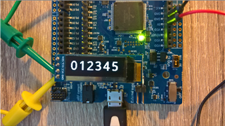
When I program the nrf9160dk with the example, the code detects the SSD1306, but the display looks like:

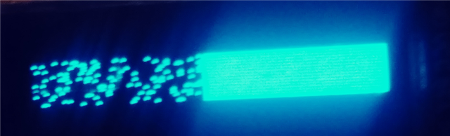
The image is only using the middle half (16 rows) of the display that has 32 rows and 128 columns. 

And the left side of the image is a random set of pixels.

What can I do to get the example to give me text on the screen?

I am using the SSD1306 OLED at: https://www.amazon.com/Pieces-Display-Module-SSD1306-3-3V-5V/dp/B08CDN5PSJ/ref=sr_1_8?dchild=1&keywords=ssd1306&qid=1606702037&sr=8-8

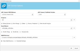
Do I have to modify any of the files to target the nRF9160 instead of the nRF52 family?

Parents
  • Here is a working solution where the whole area is in use. The result is some characters shown on the display.

    The sample code is attached:

    cfb-ncs150-oled-128x32-91dk-17-03-21.zip

    Setup:

    nRF Connect SDK: v1.5.0.

    DK: nRF9160 DK v1.0.0 (I have also had success with DK v0.9.0).

    OLED: Noname 4-pin 128x32 with SSD1306 display driver.

    The display is connected to the DK like this:

    SDA - P0.30

    SCL - P0.31

    VCC - 5V-pin on the side of the DK

    GND - GND on DK

    This is shown In the image at the top(yellow and red are connected, green and black are connected).

    Below follows step-by-step instructions showing how the above project is modified from the original 'cfb' sample. I have added a few extra details for completeness:

    1. Take a fresh copy of the Character Frame Buffer sample, cfb(v1.5.0\zephyr\samples\display\cfb).

    2. Open the prj.conf file in the cfb folder with your text editor and add the following lines:

    CONFIG_I2C=y
    CONFIG_SSD1306=y

    If you prefer white characters on black background, not the opposite, add this line as well:

    CONFIG_SSD1306_REVERSE_MODE=y

    The complete prj.conf file will then look like this:

    CONFIG_STDOUT_CONSOLE=y
    
    CONFIG_HEAP_MEM_POOL_SIZE=16384
    
    CONFIG_DISPLAY=y
    
    CONFIG_LOG=y
    
    CONFIG_CFB_LOG_LEVEL_DBG=y
    CONFIG_CHARACTER_FRAMEBUFFER=y
    
    #Add these for the SSD1306 OLED:
    CONFIG_I2C=y
    CONFIG_SSD1306=y
    
    #Reverse colors:
    CONFIG_SSD1306_REVERSE_MODE=y

    3. Next, in the project folder, 'cfb', create a file called 'nrf9160dk_nrf9160ns.overlay'

    4. Open the file and add the following:

    &i2c2 { 
        compatible = "nordic,nrf-twim";
        status = "okay";
        sda-pin = <30>;
        scl-pin = <31>;
        clock-frequency = <I2C_BITRATE_FAST>;
        zephyr,concat-buf-size = <1024>;
    
    
            ssd1306@3c {
            compatible = "solomon,ssd1306fb";
            reg = <0x3c>;
            label = "SSD1306";
            width = <128>;
            height = <32>;
            segment-offset = <0>;
            page-offset = <0>;
            display-offset = <0>; 
            multiplex-ratio = <31>;
            segment-remap;
            com-invdir;
            com-sequential;
            prechargep = <0x22>; 
        };
    };

    I have not used any shields in this project.

    5. Then open nRF Connect v3.6.1 -> Toolchain Manager -> 'Open IDE' next to nRF Connect SDK v1.5.0. and SES opens.

    6. In SES, clikc File -> Open nRF Connect SDK Project...

    7. Select your project folder. Under Board Name, select 'nrf9160dk_nrf9160ns',  check 'Clean Build Directory'.

    8. Build -> Build and Run.

    The display should now output the characters '012345'. The image is flashing rapidly, I am working on how to solve this.

    Please let me know how things works or fails.

    Best regards,

    Håkon

Reply
  • Here is a working solution where the whole area is in use. The result is some characters shown on the display.

    The sample code is attached:

    cfb-ncs150-oled-128x32-91dk-17-03-21.zip

    Setup:

    nRF Connect SDK: v1.5.0.

    DK: nRF9160 DK v1.0.0 (I have also had success with DK v0.9.0).

    OLED: Noname 4-pin 128x32 with SSD1306 display driver.

    The display is connected to the DK like this:

    SDA - P0.30

    SCL - P0.31

    VCC - 5V-pin on the side of the DK

    GND - GND on DK

    This is shown In the image at the top(yellow and red are connected, green and black are connected).

    Below follows step-by-step instructions showing how the above project is modified from the original 'cfb' sample. I have added a few extra details for completeness:

    1. Take a fresh copy of the Character Frame Buffer sample, cfb(v1.5.0\zephyr\samples\display\cfb).

    2. Open the prj.conf file in the cfb folder with your text editor and add the following lines:

    CONFIG_I2C=y
    CONFIG_SSD1306=y

    If you prefer white characters on black background, not the opposite, add this line as well:

    CONFIG_SSD1306_REVERSE_MODE=y

    The complete prj.conf file will then look like this:

    CONFIG_STDOUT_CONSOLE=y
    
    CONFIG_HEAP_MEM_POOL_SIZE=16384
    
    CONFIG_DISPLAY=y
    
    CONFIG_LOG=y
    
    CONFIG_CFB_LOG_LEVEL_DBG=y
    CONFIG_CHARACTER_FRAMEBUFFER=y
    
    #Add these for the SSD1306 OLED:
    CONFIG_I2C=y
    CONFIG_SSD1306=y
    
    #Reverse colors:
    CONFIG_SSD1306_REVERSE_MODE=y

    3. Next, in the project folder, 'cfb', create a file called 'nrf9160dk_nrf9160ns.overlay'

    4. Open the file and add the following:

    &i2c2 { 
        compatible = "nordic,nrf-twim";
        status = "okay";
        sda-pin = <30>;
        scl-pin = <31>;
        clock-frequency = <I2C_BITRATE_FAST>;
        zephyr,concat-buf-size = <1024>;
    
    
            ssd1306@3c {
            compatible = "solomon,ssd1306fb";
            reg = <0x3c>;
            label = "SSD1306";
            width = <128>;
            height = <32>;
            segment-offset = <0>;
            page-offset = <0>;
            display-offset = <0>; 
            multiplex-ratio = <31>;
            segment-remap;
            com-invdir;
            com-sequential;
            prechargep = <0x22>; 
        };
    };

    I have not used any shields in this project.

    5. Then open nRF Connect v3.6.1 -> Toolchain Manager -> 'Open IDE' next to nRF Connect SDK v1.5.0. and SES opens.

    6. In SES, clikc File -> Open nRF Connect SDK Project...

    7. Select your project folder. Under Board Name, select 'nrf9160dk_nrf9160ns',  check 'Clean Build Directory'.

    8. Build -> Build and Run.

    The display should now output the characters '012345'. The image is flashing rapidly, I am working on how to solve this.

    Please let me know how things works or fails.

    Best regards,

    Håkon

Children
Related