Hello
I am developing devices including nrf52832 and 3.3v buzzer.
However, the buzzer in this device is very hot and the battery is running out quickly.
Now I know that this buzzer is still HIGH state even when it's not in use. So, to solve this problem, I tried to output the LOW signal on the pins of the buzzer when the buzzer is not used.
However, the buzzer still does not change at the HIGH signal.
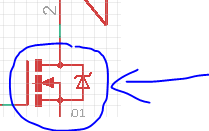
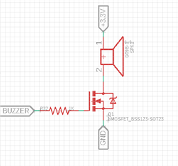
This is a my pwm code and circuit diagram about buzzer.
void pwm_play_buzzer_duration(uint32_t duration) //button buzzer
{
    uint8_t i;
    uint32_t duty = 50;

    NRF_LOG_INFO("pwm_play_buzzer_duration =>");
    ready_flag = false;

    //Set the duty cycle - keep trying until PWM is ready...
    while (app_pwm_channel_duty_set(&PWM1, 0, duty) == NRF_ERROR_BUSY);

    // ... or wait for callback.
    //while (!ready_flag);
    //APP_ERROR_CHECK(app_pwm_channel_duty_set(&PWM1, 1, duty));
    nrf_delay_ms(duration);
    app_pwm_disable(&PWM1);
}


void pwm_ready_callback(uint32_t pwm_id)    // PWM callback function
{
    NRF_LOG_INFO("pwm_ready_callback =>");
    ready_flag = true;
}

/*
 init, Once executed
 */
//buzzer PWM initializing
void pwm_init(void)
{
    ret_code_t err_code;

    /* 1-channel PWM, 200Hz, output on DK LED pins. */
    app_pwm_config_t pwm1_cfg = APP_PWM_DEFAULT_CONFIG_1CH(1500, BUZZER_PIN);

    /* Switch the polarity of the second channel. */
    pwm1_cfg.pin_polarity[1] = APP_PWM_POLARITY_ACTIVE_HIGH;

    /* Initialize and enable PWM. */
    err_code = app_pwm_init(&PWM1,&pwm1_cfg,pwm_ready_callback);
    APP_ERROR_CHECK(err_code);
    app_pwm_enable(&PWM1);
}


/*
 pwm_change_frequency,Can be executed multiple times
*/
void pwm_change_frequency(uint16_t period_us) // different sound
{
    ret_code_t err_code;

    app_pwm_disable(&PWM1); //disable PWM for change PWM
    app_pwm_uninit(&PWM1); //uninitializing a PWM

    /* 1-channel PWM, 200Hz, output on DK LED pins. */
    app_pwm_config_t pwm1_cfg = APP_PWM_DEFAULT_CONFIG_1CH(period_us, BUZZER_PIN); //original 5000L

    /* Switch the polarity of the second channel. */
    pwm1_cfg.pin_polarity[1] = APP_PWM_POLARITY_ACTIVE_HIGH;

    /* Initialize and enable PWM. */
    err_code = app_pwm_init(&PWM1,&pwm1_cfg,pwm_ready_callback);
    APP_ERROR_CHECK(err_code);
    app_pwm_enable(&PWM1);
}


void gpio_init(void)
{
  nrf_gpio_cfg_output(BUZZER_PIN); //pin25
  nrf_gpio_pin_clear(BUZZER_PIN);
}


static void do_play_buzzer(void)
{
  pwm_play_buzzer_duration(200); //buzzer play time
  app_pwm_enable(&PWM1);

  nrf_gpio_pin_clear(BUZZER_PIN); //buzzer LOW signal
}

static void do_play_buzzer_2(void) //double play buzzer test
{
  pwm_play_buzzer_duration(200); //buzzer play time
  app_pwm_enable(&PWM1);
  nrf_delay_ms(200);
  pwm_play_buzzer_duration(200); //buzzer play time
  app_pwm_enable(&PWM1);

  nrf_gpio_pin_clear(BUZZER_PIN); //buzzer LOW signal
}
Can I know about this problem?
Thank you.