This post is older than 2 years and might not be relevant anymore
More Info: Consider searching for newer posts

e-paper display with spi. (hardware pins - digital write -baud-rate)

Hello,

Sorry if it will be long. thanks for the help.

Using nrf9160 dk. The first thing I want to ask is about is the pins. I want to make sure I am using the correct pin. I think most of the pins can be used for digital I/O so that leave the sck,MISO.MOSI. 

#define sck_pin   13     //p.13
#define sda_pin   12     //p.12   MISO
#define cs_pin    11     //p.11   MOSI
#define dc_pin    21     //       digital pin pwd   
#define reset_pin 22     //       digital pin pwd
#define busy_pin  23     //       digital pin pwd
#define pnlon_pin 24     //       digital pin pwd
#define bs_pin    25     //       digital pin pwd
#define css_pin   26     //       digital pin pwd

The second thing is that I am trying to digital write to pin high/low. similar to the Arduino digital write(). So I looked and found  nrf_gpio_pin_write ( uint32_t pin_number, uint32_t value ) OR  should use gpio_pin_write(struct device *port, gpio_pin_t pin, u32_t value)

Also to set-up a pin to output/input  GPIO_INPUT /  GPIO_OUTPUT can be used right.

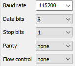
Last question to begin the serial link I couldn't find anything about that except for spi_cfg.frequency = 115200;  but that doesn't work.


I looked also into the blinky example and devicetree still confused.

Parents
  • Using nrf9160 dk. The first thing I want to ask is about is the pins. I want to make sure I am using the correct pin. I think most of the pins can be used for digital I/O so that leave the sck,MISO.MOSI. 

    You should look at the backside of the nRF9160 DK what pins are occupied by the Development Kit. If you want to re-route them to the physical pins on the DK, check out Didrik's answer in this ticket for instructions on how to go about it. It seems like P0.26 is the only one that is used by the DK.

    By the way, you should not configure the pins in your source code (.c or .h files), hardware configurations should get done in DTS using an overlay file. Take a look at 1.2 Walkthrough for BME280 to get an intutition of how to go about this.

    The second thing is that I am trying to digital write to pin high/low. similar to the Arduino digital write(). So I looked and found  nrf_gpio_pin_write ( uint32_t pin_number, uint32_t value ) OR  should use gpio_pin_write(struct device *port, gpio_pin_t pin, u32_t value)

    It is always good practice to use the highest abstraction layer-->the Zephyr API. However, in the newest versions of NCS, the function gpio_pin_write() is no longer present. In the newest versions of NCS, you should use the function gpio_pin_set() to set the logical level of an output pin.

    Also to set-up a pin to output/input  GPIO_INPUT /  GPIO_OUTPUT can be used right.

     Yes, these can be used when configuring the pin through gpio_pin_configure(). Take a look at the sample ncs\v1.4.0\zephyr\samples\bluetooth\hci_spi\src\main.c how to go about this:

    Best regards

    Simon

  • Hi Simon,

    Thanks for the feedback. I took your advice. for setting the input/out and writing to a pin. For now no error when building

    struct device *dev;
    dev = device_get_binding("GPIO_0");
    
    Digital write
    
    gpio_pin_set(dev,12,1);
    else gpio_pin_set(dev,12,0 );
    
    Setting the pin to input/output
    gpio_pin_configure(dev,25,GPIO_OUTPUT);
    gpio_pin_configure(dev,23,GPIO_INPUT);

    I have the pins in the overlay file. Do I need to go into the nrf9160......_common.dts and change something from  there or overlay will take care of that.

    &spi3 {
      compatible ="nordic,nrf_spim";
      current-speed = <115200> ;
      status = "ok";
      sck-pin = <13>;
      sda_pin = <12>;
      cs_pin = <11>;
      dc_pin = <21>;
      reset_pin = <22>;
      busy_pin = <23>;
      pnlon_pin = <24>;
      bs_pin = <25>;
      css_pin = <26>;
      label = "SPI_display"
      spi-max-frequency = <8000000>;
    };
    
    &gpio0 {
    status = "ok";	
    }

    CONFIG_SPM=y
    CONFIG_TRUSTED_EXECUTION_NONSECURE=y
    CONFIG_STDOUT_CONSOLE=y
    CONFIG_LOG=y
    CONFIG_LOG_DEFAULT_LEVEL=4
    CONFIG_HEAP_MEM_POOL_SIZE=16384
    # SPI
    CONFIG_SERIAL=y
    CONFIG_SPI=y
    CONFIG_SPI_3=y
    #CONFIG_SPI_SLAVE =y
    #CONFIG_SPI_3_NRF_SPIM=y
    CONFIG_SPI_3=y
    CONFIG_SPI_NRFX=y
    #CONFIG_SPI_3_OP_MODES =y
    CONFIG_MAIN_STACK_SIZE=4096
    #GPIO
    CONFIG_GPIO=y
    CONFIG_PRINTK=y
    CONFIG_LOG_PRINTK=y


    Also for gpio read I am using gpio_pin_get() . Lastly what is the function if there is for starting the serial communication. 

  • Why are you using the GPIO peripheral to communicate with the display? You should instead use the SPI peripheral.

    Instead of using the function gpio_pin_set(), use the function spi_transceive().

    The reason the below code crashes is because you're getting the binding to an spi instance, and using functions (gpio_pin_set()) intended for a GPIO binding.

    struct device *dev;
    dev = device_get_binding("spi3");
    
      for ( int i = 0; i < 8; i++ ) {
        if ((( data >> (7 - i) ) & 0x01 ) == 1 ) 
        gpio_pin_set(dev,miso_pin, 1 );
        else gpio_pin_set(dev, miso_pin, 0 );
        gpio_pin_set(dev,sck_pin, 1 );
        gpio_pin_set(dev,sck_pin, 0 );
      }

    I would recommend you to look at some SPI samples to see how to use the SPI functions. E.g. sdk-zephyr/main.c at 3366927a54986ad0ddf060d0e08ecc578adf11f0 · nrfconnect/sdk-zephyr · GitHub

    What kind of display are you using? It may be some already working examples/drivers that you can use: sdk-zephyr/samples/display at 3366927a54986ad0ddf060d0e08ecc578adf11f0 · nrfconnect/sdk-zephyr · GitHub, where you use a higher abstraction layer than the SPI functions.

    Best regards,

    Simon

  • The display I am using is pervasive display 12 inch, looked into the available display examples nothing is really relevant and quite limited. Since I am setting the pins output so went with GPIO, digitally write to the pin so, went with the function you recommended (gpio_pin_set).will have a look into the SPI functions.

  • Initially I thought that you were going to use gpio_pin_set() for something else, sorry for confusing you. Please ask more question if you don't get it to work using the SPI functions. If you're new to NCS it can be a bit overwhelming, but as soon as you've learned about the different abstraction layers, Kconfigs and the device tree it's much easier to work with.

    Best regards,

    Simon

  • Thanks, I am slowly getting the hang of it. Couple more question. The following code is the one runs on the arduino MKR1500 I created for the Pervasive display it works without any problems. It doesn't use any spi funcations. I tried to follow that with the nRF.  The code as you can see I am using gpio functions. 


    That's why I tried to use the gpio_configure , gpio_set , gpio_ get funcations. 

    If I start using the spi functions how is it going to look like. what other function I might use for the read and configuration of the pins (output,input) or should I stick with using the gpio.

    Other issue the printk is not printing does that mean the code is running?? 

  • It guess it should work to use GPIOs to communicate with the display, by emulating SPI, but that makes everything much more complex and ineficcient. Instead of writing one line using the SPI peripheral, maybe you end up with 10 lines using the GPIOs instead.

    spi_loop.zip

    Test out the sample above with the nrf9160dk. It is a loopback sample where the nRF9160 both sends and receives data (to itself). Connect  P0.11 and P0.12 together to enable the loopback.

    When you get that to work, you know how to both send and receive data with SPI, which is all you need. Then you can modify it to communicate with the Display. You should study the datasheet of your display of how to communicate with it.

    AMG said:
    Other issue the printk is not printing does that mean the code is running?? 

    That might be, but you don't know for certain. It may be something wrong with how you set up the logging. Test out the sample zephyr/samples/hello_world, and open a termite terminal with these setting:

    Best regards,

    Simon

Reply
  • It guess it should work to use GPIOs to communicate with the display, by emulating SPI, but that makes everything much more complex and ineficcient. Instead of writing one line using the SPI peripheral, maybe you end up with 10 lines using the GPIOs instead.

    spi_loop.zip

    Test out the sample above with the nrf9160dk. It is a loopback sample where the nRF9160 both sends and receives data (to itself). Connect  P0.11 and P0.12 together to enable the loopback.

    When you get that to work, you know how to both send and receive data with SPI, which is all you need. Then you can modify it to communicate with the Display. You should study the datasheet of your display of how to communicate with it.

    AMG said:
    Other issue the printk is not printing does that mean the code is running?? 

    That might be, but you don't know for certain. It may be something wrong with how you set up the logging. Test out the sample zephyr/samples/hello_world, and open a termite terminal with these setting:

    Best regards,

    Simon

Children
  • I appreciate all the help, will give it a try. One last thing can you do a quick check and try to see if you can spot anything wrong with the config files or I need to add something to the dts files before I start with a different approach. 

      pin connections (sck: p0.13- MISO p0.12 -  MOSI p0.11 ) ( From p0.20   to p0.25 digital pwm pins) 


    prj.conf

    CONFIG_SPM=y
    CONFIG_TRUSTED_EXECUTION_NONSECURE=y
    CONFIG_STDOUT_CONSOLE=y
    CONFIG_LOG=y
    CONFIG_LOG_DEFAULT_LEVEL=4
    CONFIG_HEAP_MEM_POOL_SIZE=16384
    
    
    # SPI
    
    CONFIG_SERIAL=y
    CONFIG_SPI=y
    CONFIG_SPI_3=y
    #CONFIG_SPI_SLAVE =y
    #CONFIG_SPI_3_NRF_SPIM=y
    CONFIG_SPI_3=y 
    CONFIG_SPI_NRFX=y
    #CONFIG_SPI_3_OP_MODES =y
    CONFIG_MAIN_STACK_SIZE=4096


    #GPIO
    
    CONFIG_GPIO=y
    CONFIG_PRINTK=y
    CONFIG_LOG_PRINTK=y


    overlay

    &spi3 {
      status = "ok"; 
      current-speed = <115200> ;
      sck-pin = <13>;
      miso_pin = <12>;
      mosi_pin = <11>;
      label = "SPI_3";
    };
    
    &gpio0 {
    status = "ok";	
    };


    Pin connection. 

    #define SCK_pin   13     //p.13
    #define MISO_pin   12     //p.12   MISO
    #define MOSI_pin    11     //p.11   MOSI
    #define DC_pin    20     // p0.20       digital pin pwm   
    #define RESET_pin 21     //  p0.21     digital pin pwm
    #define BUSY_pin  22     // p0.22      digital pin pwm
    #define PNLON_pin 23     // p0.23      digital pin pwm
    #define BS_pin    24     // p0.24       digital pin pwm
    #define CSS_pin   25     // po.25      digital pin pwm

  • I Managed to get it to work. Thanks for all your help Simon. 

Related