

Hello Nordic Team,
i'm trying to configure the nRF52833 DK to scan through two channels at a high rate (10ksps) with the SAADC module. i have configured the time to operate at 100us and I am seeing what looks like settling time with the internal mux. for reference i used the following configuration in the ADC:
void saadc_init(void)
{
    ret_code_t err_code;
    //nrf_saadc_channel_config_t channel_config =
    //    NRF_DRV_SAADC_DEFAULT_CHANNEL_CONFIG_SE(NRF_SAADC_INPUT_AIN0);
    nrf_drv_saadc_config_t saadc_config;
    nrf_saadc_channel_config_t channel_config;

    saadc_config.low_power_mode = true;
    saadc_config.resolution = NRF_SAADC_RESOLUTION_12BIT;
    saadc_config.oversample = NRF_SAADC_OVERSAMPLE_DISABLED;
    saadc_config.interrupt_priority = APP_IRQ_PRIORITY_LOW_MID;

    err_code = nrf_drv_saadc_init(&saadc_config, saadc_callback);
    APP_ERROR_CHECK(err_code);

    channel_config.acq_time = NRF_SAADC_ACQTIME_3US;
    channel_config.reference = NRF_SAADC_REFERENCE_INTERNAL;
    channel_config.gain = NRF_SAADC_GAIN1_2;
    channel_config.mode = NRF_SAADC_MODE_SINGLE_ENDED;
    channel_config.pin_p = NRF_SAADC_INPUT_AIN1;
    channel_config.pin_n = NRF_SAADC_INPUT_DISABLED;
    channel_config.resistor_p = NRF_SAADC_RESISTOR_DISABLED;                              //Disable pullup resistor on the input pin
    channel_config.resistor_n = NRF_SAADC_RESISTOR_DISABLED;                              //Disable pulldown resistor on the input pin

    err_code = nrf_drv_saadc_channel_init(0, &channel_config);
    APP_ERROR_CHECK(err_code);

    channel_config.acq_time = NRF_SAADC_ACQTIME_3US;
    channel_config.reference = NRF_SAADC_REFERENCE_INTERNAL;
    channel_config.gain = NRF_SAADC_GAIN1_2 ;
    channel_config.mode = NRF_SAADC_MODE_SINGLE_ENDED;
    channel_config.pin_p = NRF_SAADC_INPUT_AIN2;
    channel_config.pin_n = NRF_SAADC_INPUT_DISABLED;
    channel_config.resistor_p = NRF_SAADC_RESISTOR_DISABLED;                              //Disable pullup resistor on the input pin
    channel_config.resistor_n = NRF_SAADC_RESISTOR_DISABLED;                              //Disable pulldown resistor on the input pin

    err_code = nrf_drv_saadc_channel_init(1, &channel_config);
    APP_ERROR_CHECK(err_code);


    err_code = nrf_drv_saadc_buffer_convert(m_buffer_pool[0], SAMPLES_IN_BUFFER);
    APP_ERROR_CHECK(err_code);

    err_code = nrf_drv_saadc_buffer_convert(m_buffer_pool[1], SAMPLES_IN_BUFFER);
    APP_ERROR_CHECK(err_code);

}
the timer is setup as follows:
void saadc_sampling_event_init(void)
{
    ret_code_t err_code;

    err_code = nrf_drv_ppi_init();
    APP_ERROR_CHECK(err_code);

    nrf_drv_timer_config_t timer_cfg = NRF_DRV_TIMER_DEFAULT_CONFIG;
    timer_cfg.bit_width = NRF_TIMER_BIT_WIDTH_32;
    err_code = nrf_drv_timer_init(&m_timer, &timer_cfg, timer_handler);
    APP_ERROR_CHECK(err_code);

    /* setup m_timer for compare event every 100us*/
    uint32_t ticks = nrf_drv_timer_us_to_ticks(&m_timer, 100);
    nrf_drv_timer_extended_compare(&m_timer,
                                   NRF_TIMER_CC_CHANNEL0,
                                   ticks,
                                   NRF_TIMER_SHORT_COMPARE0_CLEAR_MASK,
                                   false);
    nrf_drv_timer_enable(&m_timer);

    uint32_t timer_compare_event_addr = nrf_drv_timer_compare_event_address_get(&m_timer,
                                                                                NRF_TIMER_CC_CHANNEL0);
    uint32_t saadc_sample_task_addr   = nrf_drv_saadc_sample_task_get();

    /* setup ppi channel so that timer compare event is triggering sample task in SAADC */
    err_code = nrf_drv_ppi_channel_alloc(&m_ppi_channel);
    APP_ERROR_CHECK(err_code);

    err_code = nrf_drv_ppi_channel_assign(m_ppi_channel,
                                          timer_compare_event_addr,
                                          saadc_sample_task_addr);
    APP_ERROR_CHECK(err_code);
}
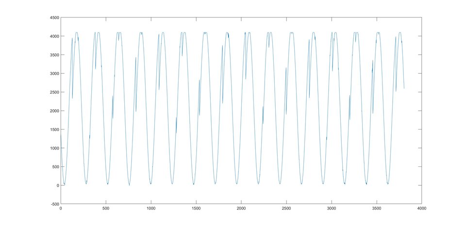
i used a 50Hz test tone connected to both of the AIN pins configured. i get what looks like unsettled data (i plotted only a single channel in this case, using every other sample as ch0, and a similar plot is achieved using ch1).
if i slow the sample rate down to 1kHz, the results improves as per the below:
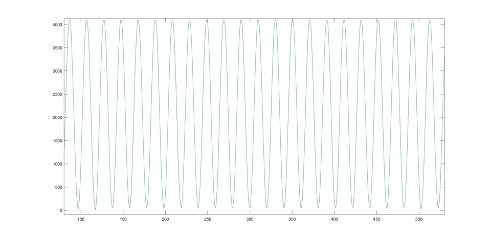
I would have thought that the input mux could scan between two samples and settle faster than 10ksps accurately. I likely have configured something incorrectly. any guidance or advice is greatly appreciated!
Kind regards,

