This post is older than 2 years and might not be relevant anymore
More Info: Consider searching for newer posts

Thingy91 Power consumption

Hi Dev team,

I am working around with the Thiny91 and wanted to have more information regarding the power consumption characteristics of the board.

I have a program running on the Thingy91 that connects to my server to send sensor data through MQTT, every 5 mins. In the meantime, I want to go into the lowest power consumption mode and wake up only to send data and then back to the low power mode in between.

I currently have a power consumption of around 1.5 mA in the low power mode and I want to reduce it further to the datasheet values. I also have enabled PSM mode with : 

CONFIG_LTE_PSM_REQ_RPTAU="10101010"
CONFIG_LTE_PSM_REQ_RAT="00000001"

and I see that it is configured by the network correctly as well. 

I had a few questions regarding the power consumption of the Thingy91 board :

(1). I get sensor data through my UART every 5 mins, so I cant have CONFIG_SERIAL = n in my prj.conf . That maybe 1 cause for this significantly high power consumption. Can I enable and disable the UART in runtime and will that make any difference to the power consumption in this case.

(2). The Thingy91 user guide says that , the 3.3V power domain can be powered down to save power when Thingy91 is in sleep mode. How can this be done ?

(3). Will it be logical to turn off the modem in order to save power during the sleep mode ?  

(4). Does modem firmware affect the power measurements ?

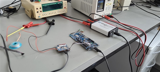
(5). To measure power power consumption, I use Joulescope and remove the USB power to the Thingy91. Thus, I am unable to view the logs in my link monitor when measuring power. Is there any other way to view the logs while measuring current (like Segger RTT Viewer) and how do I enable that .

(6). Any other power saving tips that could help reduce power for the Thingy91.

Regards,

Adeel. 

Parents
  • Hi,

    (1). I get sensor data through my UART every 5 mins, so I cant have CONFIG_SERIAL = n in my prj.conf . That maybe 1 cause for this significantly high power consumption. Can I enable and disable the UART in runtime and will that make any difference to the power consumption in this case.

    Yes, you can enable and disable the UART at runtime. One way to do it is to use the power management API in zephyr. This will make a difference in power consumption. The UART consumes about 4-600 uA. By turning it off you should ideally get down to 3-4 uA (unless something else is consuming power as well of course).

    #include <device.h>
    #include "power/power.h"
    
    const struct device *console, *uart1;
    
    void main(void)
    {
      // Turn off logging (which is using UART0):
      console = device_get_binding(DT_LABEL(DT_CHOSEN(zephyr_console)));
      device_set_power_state(console, DEVICE_PM_OFF_STATE, NULL, NULL);
      
      // Turn off UART1:
      uart1 = device_get_binding(DT_LABEL(DT_NODELABEL(uart1)));
      device_set_power_state(uart1, DEVICE_PM_OFF_STATE, NULL, NULL);
      
      .......
    
    }

    and in prj.conf:

    CONFIG_DEVICE_POWER_MANAGEMENT=y


    (2). The Thingy91 user guide says that , the 3.3V power domain can be powered down to save power when Thingy91 is in sleep mode. How can this be done ?

     Yes that is correct. I see that you already figured this out in your previous answer. You can use the adp536x library functions

    adp536x_init(ADP536X_I2C_DEV_NAME);
    adp536x_buckbst_enable(false);


    (3). Will it be logical to turn off the modem in order to save power during the sleep mode ?  

    Usually you would just send the AT+CFUN=0 command to disconnect from the network and let the modem stay in idle mode. You can then issue new AT commands for reconnecting. Or you can use the LTE link control API. Something link this:

    #include <modem/lte_lc.h>
    
    void main(void){
      int err;
      err = lte_lc_offline();
      
      ......
      
    }

    And in prj.conf:

    CONFIG_NETWORKING=y
    CONFIG_NET_SOCEKTS=y
    CONFIG_NET_SOCKETS_OFFLOAD=y
    
    CONFIG_AT_HOST_LIBRARY=y
    CONFIG_BSD_LIBRARY=y
    
    CONFIG_LTE_LINK_CONTROL=y
    #do not automatically connect to the network:
    CONFIG_LTE_AUTO_INIT_AND_CONNECT=n

    You should get a current consumption of 2.2uA in this mode.

    Alternatively, if the network supports it, you can use PSM mode. In PSM mode the modem is in sleep, but you are still attached to the network, meaning that the energy needed to reconnect to the network is minimal, since it does not have to do the scanning procedure etc. The idle current in PSM mode is 2.7uA.


    (4). Does modem firmware affect the power measurements ?

    The modem FW should not affect the power measurements when the modem is turned off. If the modem is turned on and connected/trying to connect to the network it will affect the current consumption.


    (5). To measure power power consumption, I use Joulescope and remove the USB power to the Thingy91. Thus, I am unable to view the logs in my link monitor when measuring power. Is there any other way to view the logs while measuring current (like Segger RTT Viewer) and how do I enable that .

     If you want to measure current at the same time as you see the logs you should leave the USB cable plugged in and use the default UART logging module. You can still measure current to the nRF91 and nRF52 through the current measurement headers. However, this is not very useful for debugging current consumption, since the UART module is consuming current. You can turn off RX in the logging module to save some power. NRF_UARTE0->TASKS_STOPRX = 1; And the UART will consume about 50uA instead of 600uA.

    You can use RTT as well if you have a debugger that supports RTT, and connected it to the SWD header. The problem is that in order to use RTT the chip has to be in debug mode, which is consuming 3-4 mA. So it's not that useful at all when measuring current.


    (6). Any other power saving tips that could help reduce power for the Thingy91.

     You should start with a simple project where you get the 3-4 uA idle current, and then add one peripheral/feature after another.

    You can also try System OFF mode which will completely shut down the nRF91 and then see what floor current you are able to achieve, and use that as a base line for later measurements.

    Remember that on the thingy91 there are both a nRF91 and a nRF52. If you are not going to use the nRF52 you might want to consider putting this to system OFF mode to save current. Check out the thingy91 schematics to see which external sensors are connected to which nRF chip.

  • Hi Stian,

    Thanks for the detailed answer Slight smile.

    You can also try System OFF mode which will completely shut down the nRF91 and then see what floor current you are able to achieve, and use that as a base line for later measurements.

    Yes, I am using the System Off sample in the zephyr folder as a base line. I have progressed further and I am now able to achieve a current of around 120 uA. I understand that the Thingy91 has nRF91, nrf52 and other external sensors that add to the power consumption as a whole.

    I turned off the UART now by CONFIG_SERIAL = n both in spm and the application.

    I also turned the 3.3 V supply so the LED's, color sensor, buzzer all are off due to this. 

    If you are not going to use the nRF52 you might want to consider putting this to system OFF mode to save curren

    I further want to reduce the current to around 20-30uA. I am not using the nrf52 so I want to switch it off as well. How can this be done ?

    Further, I wanted to know how much current the BME680 environment sensors and the adxl362 accelerometer consumes, and how could I turn it off as I don't need that as well right now. 

    Regards,

    Adeel.

  • Hi Stian,

    I see that the current to the nRF52840 is about 2.0 mA. This is expected when the USB cable is plugged in. As soon as you pull out the USB cable, the UART and USB interface will shut down and the nRF52840 will go into system OFF mode.

    I measured this current while the USB cable was unplugged. I did not have the USB cable plugged in.

    I had just powered my board through a 3.5 V supply on TP13 to the LiPo power input and did not have anything else connected to the Thingy.

    Is there something else that I am missing here ? 

    Regards,

    Adeel.

  • Hi, can you try to flash the following hex to the nrf52840?

    3644.merged.hex

    This is the connectivity FW, which I tested out here.

    Do you remember to flip the switch to nRF52, when programming the nRF52?

    Also when building the connectivity FW, do you build for target thingy91_nrf52840?

  • Hi Stian,

    Do you remember to flip the switch to nRF52, when programming the nRF52?

    Also when building the connectivity FW, do you build for target thingy91_nrf52840?

    Yes, I did this. I flipped the SW2 to nrf52 first. Then, I built the connectivity bridge application for thingy91_nrf52840. I have a nrf9160DK as my external debug probe through which I flashed the merged.hex file on the nrf52.

    I will try out your hex file and let you know asap :). Thanks for the help on this Slight smile.

    Regards,

    Adeel.

  • Hi Stian,

    I tried your merged.hex file but unfortunately the current consumption remained the same (120uA) on the LiPo input. 

    Right now, I have currents like these : nrf9160 -> 2.6 uA (bme680 sensor sample), nrf52840 -> 1.8mA (connectivity bridge sample), Thingy91 board current through LiPo power measuremnt -> approx 120uA.

    This is when there is no USB connected to the Thingy91. No external connection apart from the 3.5 V power supply. 

    What I could infer is that the process of the connectivity bridge sample is not happening correctly.

    I will explain you my procedure in building the connectivity bridge sample :- 

    (1). I have a bme680 sensor sample running on the nrf9160.

    (2). Then, I switch the SW2 to nrf52 and open the connectivity bridge sample for thingy91_nrf52840.

    (3). I build the sample and upload it through the programmer and nrf9160DK external debugger. 

    At this time, I have my USB cable connected to Thingy91 when the program is being uploaded through thingy91.

    I also  see this on my PC after program is uploaded :-

    This is when the USB cable is connected to the Thingy91. I assume this should happen if the connectivity bridge application is uploaded correctly. Then I unplug my USB cable and turn on my LiPo power (external 3.5V) to measure the current. 

    I see an average current of 120uA.

    The issue is that I see the 1.8mA current on the nrf52840 even when the USB is unplugged, so I assume this extra current is due to that.

    Could you guide me as to what could be wrong here ? Sorry for the trouble but I am really stuck with this here Disappointed.

    I am also attaching my merged.hex file of the connectivity bridge sample : 2273.merged.hex

    Regards,

    Adeel.

Reply
  • Hi Stian,

    I tried your merged.hex file but unfortunately the current consumption remained the same (120uA) on the LiPo input. 

    Right now, I have currents like these : nrf9160 -> 2.6 uA (bme680 sensor sample), nrf52840 -> 1.8mA (connectivity bridge sample), Thingy91 board current through LiPo power measuremnt -> approx 120uA.

    This is when there is no USB connected to the Thingy91. No external connection apart from the 3.5 V power supply. 

    What I could infer is that the process of the connectivity bridge sample is not happening correctly.

    I will explain you my procedure in building the connectivity bridge sample :- 

    (1). I have a bme680 sensor sample running on the nrf9160.

    (2). Then, I switch the SW2 to nrf52 and open the connectivity bridge sample for thingy91_nrf52840.

    (3). I build the sample and upload it through the programmer and nrf9160DK external debugger. 

    At this time, I have my USB cable connected to Thingy91 when the program is being uploaded through thingy91.

    I also  see this on my PC after program is uploaded :-

    This is when the USB cable is connected to the Thingy91. I assume this should happen if the connectivity bridge application is uploaded correctly. Then I unplug my USB cable and turn on my LiPo power (external 3.5V) to measure the current. 

    I see an average current of 120uA.

    The issue is that I see the 1.8mA current on the nrf52840 even when the USB is unplugged, so I assume this extra current is due to that.

    Could you guide me as to what could be wrong here ? Sorry for the trouble but I am really stuck with this here Disappointed.

    I am also attaching my merged.hex file of the connectivity bridge sample : 2273.merged.hex

    Regards,

    Adeel.

Children
No Data
Related