This post is older than 2 years and might not be relevant anymore
More Info: Consider searching for newer posts

Optimal load impedance NRF52832

Hi,

I am doing some research for the antenna matching of the NRF52832. Now the product specification v1.4 on page 551 states:

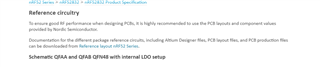
"A matching network is needed between the RF pin ANT and the antenna, to match the antenna impedance (normally 50 ohm) to the optimum RF load impedance for the chip. For optimum performance, the impedance for the matching network should be set as described in the recommended package reference circuitry in Reference circuitry on page 545 above."

But the link is dead. Ive tried searching for documents that could be the one that they are trying to link to. however in none of the documents I can find the 'optimal load impedance' of the NRF52. So, What is the optimal load impedance of the NRF52832 (-CIAA)?

Kind regards,

Ruben

Parents
  • Hi,

    Sorry for the late reply. Can you send me a screenshot and point out where did you find the dead link?

    The reference circuitry for nRF52832 are on page 545 of the product specification in you are using the PDF version, or you can find the same chapter in the infocenter: https://infocenter.nordicsemi.com/index.jsp?topic=%2Fcom.nordic.infocenter.nrf52832.ps.v1.1%2Fref_circuitry.html&anchor=concept_aqp_fd1_fq

    (scroll down to find schematics for CIAA)

    The matching network for the nRF52832 consist of 2 components for CIAA package, C3 and L1.

    In addition to the matching network for the nRF52832 (radio) you should add a matching network for your antenna (PI network). So your matching circuit will end up looking like this:

    The values for the antenna matching components are usually found after tuning of the antenna in the lab. For the radio matching components start with the values used in the reference circuit, but they may still need some tuning depending on how closely you have followed the reference layout for the radio matching components.

    Best regards,

    Marjeris

  • Hi Marjeris,

    Thank you for you answer.

    About the link: If i click on this link  I get an "Page not found"

    About My question:

    To rephrase my question a bit different:

    Ive done projects with an semtech radio. They specify an Zopt (optimal load impedance) in the form of '10+j64 ohm' for example. Which should be the complex conjugent of the source impedance, in our case the nRF52832.

    So what I need from you is the zopt of the nRF52832CIAA, so that I can match the antenna.

    I understand what you mean with your answer: By adding the C3 and L1, the system at netlabel 'RF' should be 50 Ohm. And when that is 50 Ohm, you can match the antenna with the Pi network to also match 50 ohm. And when both those conditions match you should theoretically have an optimal system.

    However this leads to 2 problems as far as I can see it:

    1) My pcb and your pcb are not 100% identical, so there will be different parasitical effects. So I probablt will need slightly different values to get the same result. 

    2) We already send the pcb for manufacturing, and my collegue who designed this circuit thought that C3 and L3 were the only components needed for the matching. Luckely in a review i suggested to add 2 more components so that we could add an pi- network or T-network (because I like to keep my options open). So this means that I have 2 out of the 3 components of 'your' Pi network. So using the method you suggested I might be able to match the circuit if I dont need the third component. 

    So I rather get the 'Zopt' from you, and directly match the antenna (using C3, L1 C17 and C19). Not to 50 Ohm, but to 'Zopt'. So I dont have to deal with the missing component of the Pi-network, and the parasitic differences.

    I hope I explained my question clearly.

    Regards,

    Ruben

Reply
  • Hi Marjeris,

    Thank you for you answer.

    About the link: If i click on this link  I get an "Page not found"

    About My question:

    To rephrase my question a bit different:

    Ive done projects with an semtech radio. They specify an Zopt (optimal load impedance) in the form of '10+j64 ohm' for example. Which should be the complex conjugent of the source impedance, in our case the nRF52832.

    So what I need from you is the zopt of the nRF52832CIAA, so that I can match the antenna.

    I understand what you mean with your answer: By adding the C3 and L1, the system at netlabel 'RF' should be 50 Ohm. And when that is 50 Ohm, you can match the antenna with the Pi network to also match 50 ohm. And when both those conditions match you should theoretically have an optimal system.

    However this leads to 2 problems as far as I can see it:

    1) My pcb and your pcb are not 100% identical, so there will be different parasitical effects. So I probablt will need slightly different values to get the same result. 

    2) We already send the pcb for manufacturing, and my collegue who designed this circuit thought that C3 and L3 were the only components needed for the matching. Luckely in a review i suggested to add 2 more components so that we could add an pi- network or T-network (because I like to keep my options open). So this means that I have 2 out of the 3 components of 'your' Pi network. So using the method you suggested I might be able to match the circuit if I dont need the third component. 

    So I rather get the 'Zopt' from you, and directly match the antenna (using C3, L1 C17 and C19). Not to 50 Ohm, but to 'Zopt'. So I dont have to deal with the missing component of the Pi-network, and the parasitic differences.

    I hope I explained my question clearly.

    Regards,

    Ruben

Children
  • Hi Ruben,

    The Zopt is not so important in this case, I will try to explain why. However good match on impedance you do to Zopt, you still need to measure harmonics, and adjust your matching based on this. Therefore my recomendation was to just measure the output power and harmonics, and don't bother with the impedance of the radio. When the output power is around +4dBm and the harmonics are under threshold, with a 50ohm load (using a spectrum analyzer) then per definition the radio will be matched to optimal Zopt.

Related