This post is older than 2 years and might not be relevant anymore
More Info: Consider searching for newer posts

NRF52832 power leakage

We use NRF52832   in the remote control of the car。We measured the average current of power consumption at about 1uA.Every 300ms, the current curve bounces to the transient current of 100uA, which we suspect is caused by charging and discharging of the DEC4 decoupling capacitor.We used the power supply of CR2032 to make 2000 samples. 10% of the samples ran out of battery power one month after they appeared. Theoretically, the battery could survive two years without changing.We did not initialize the idle pins, including NFC pin.I don't know what caused our power consumption. The real-time current of the sample retest was normal 1UA.We used SPIS, if configured "nrf_spis_pins_set(NRF_SPIS1,SPI_CLK_PIN,SPI_MOSI_PIN,NULL,SPI_CS_PIN)" This is going to affect the control of idle IO and I don't know what's wrong with the configuration。We also used PPI, mapped timer interrupt events, and GPIO rolloff。"nrf_power_system_off "The PPI needs to be turned off before the function, otherwise the power cannot be reduced.

  •  “nrf_gpio_cfg(LED_RED,    NRF_GPIO_PIN_DIR_INPUT,NRF_GPIO_PIN_INPUT_DISCONNECT,NRF_GPIO_PIN_PULLUP,NRF_GPIO_PIN_S0S1,NRF_GPIO_PIN_NOSENSE);”I don't really understand what NRF_GPIO_PIN_INPUT_DISCONNECT means,When I set pullup and disconnect ,the LED is off. set pulldown and disconnect the light is on .
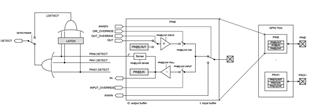
  • According to the block diagram, shouldn't the light be off as long as I set it off, no matter whether I pull it up or down?
Parents
  • The nRF52832 data sheet is incorrect, and the drawing you show is also incorrect. The pull-up and pull down resistors are applied to the port pin regardless of whether the port is set as input or output or unconnected. This means that the internal pull-down supplies power to the LED even if set to Input and Disconnect. I spent some time proving this. The answer to disable the LED leakage is to turn off the pull-down by using PULLNONE.

    Note LEDs vary a lot; some might appear lit and others not; the pull-up or pull-down are about 13k, but the LED voltage drop varies from part to part and of course the coin cell voltage changes depending on pulse load and recovery time. What capacitance is used as a reservoir on the coin cell, and is this capacitor ceramic or Tantalum? If ceramic, what voltage rating is the capacitor? It matters ..

    Also what level of illumination is directed at the LED when installed, eg from a car light other than the LED or sunlight? Maybe show the circuit schematic. You can test the illumination level issue; shine the brightest LED torch you can find at the assembly, particularly the LEDs, and see if the measured leakage changes.

    SPIS should not have pull-ups enabled, except perhaps on /CS if the driver is expected to be disconnected. If there are issues with insufficient pin drive on SPIS the master could be thrashing the slave due to bus errors; just like leaves in sunshine this can exhaust a battery. Some guard timer might help, one SPIS request accepted every minute .. any pin left high or with pull-up enabled while a connected device powers down will try to phantom power the connected device.

  • and is this capacitor ceramic or Tantalum? If ceramic, what voltage rating is the capacitor? It matters ..

    Ceramic capacitor, 50V withstand voltage

    0603 Conventional packaging LED

    Thanks for your proof. Is there a correct datasheet?

    • If it is an LED leak, check the static power consumption should be detected.

      • My average static power consumption right now is very low.Capacitor leakage has also occurred, but static power consumption can be measured, which is problematic.

      • It's an occasional leak, and it's not as easy to catch the leak
  • 50V is fantastic, no issues with ceramic headroom there; you didn't mention the capacitance though, and 50V might imply not much; I advise minimum 100uF for CR2032 and BLE operation, more is better. The CR2032 is not the power source, instead it is the trickle charger for the capacitor; the BLE burst transmission uses the capacitor, not the coin cell - well, that is if you want to get close to coin cell capacity usage.

    If leak is occasional, usual reason is some clock left on in sleep, such as SAADC or UART or PWM or SPI not terminating properly. Not terminating properly is usually caused by issuing a STOP and not waiting for the STOPPED event; if using the library code that should be handled, but anything pre-v17.0.2 has to be regarded with suspicion. I use low-level drivers. Maybe have the cpu measure its own current consumption, then on wakeup it can take a port snapshot and log to see if anything (such as pull-down) is amiss. Maybe the pull-down is not disabled after an LED blinks on just when going to sleep; that's at least 80uA right there.

    If you are using IRDA or other optical sense by any chance, tree leaves rippling in sunshine can cause unexpected wakeups as they look like data transmission requests; I kid you not, this drained batteries on an industrial outdoor application some years back.

    Where is the voltage for the tri-colour LED coming from? Is there a boost regulator for when the coin cell voltage is down at 2.6 volts, or do the LEDs just go dim?

  • If you are using IRDA or other optical sense by any chance, tree leaves rippling in sunshine can cause unexpected wakeups as they look like data transmission requests; I kid you not, this drained batteries on an industrial outdoor application some years back.

    I believe what you said about my friend.There is indeed invisible optical communication.

    but anything pre-v17.0.2 has to be regarded with suspicion.
    • By version do you mean SDK version?

      • I used the nRF5 SDK 15.2.0...BLE use the flash_s132_nrf52_6.1.0_softdevice

      • Maybe the version is too old, but if I were to change the SDK now, I would need to find a clear usage bug to convince my colleagues.Do you know what's wrong with the version.
        Maybe have the cpu measure its own current consumption, then on wakeup it can take a port snapshot and log to see if anything (such as pull-down) is amiss.
        • This is a very good suggestion. How to monitor the running power of 52832 itself

          Is there a boost regulator for when the coin cell voltage is down at 2.6 volts, or do the LEDs just go dim

          The button battery is directly used for power supply without any boost measures. I set the low voltage threshold of 52832 at 2.4V without any operation and directly hibernate.

          • The largest energy storage capacitor on the board is 4.7UF on the datasheet.

Reply
  • If you are using IRDA or other optical sense by any chance, tree leaves rippling in sunshine can cause unexpected wakeups as they look like data transmission requests; I kid you not, this drained batteries on an industrial outdoor application some years back.

    I believe what you said about my friend.There is indeed invisible optical communication.

    but anything pre-v17.0.2 has to be regarded with suspicion.
    • By version do you mean SDK version?

      • I used the nRF5 SDK 15.2.0...BLE use the flash_s132_nrf52_6.1.0_softdevice

      • Maybe the version is too old, but if I were to change the SDK now, I would need to find a clear usage bug to convince my colleagues.Do you know what's wrong with the version.
        Maybe have the cpu measure its own current consumption, then on wakeup it can take a port snapshot and log to see if anything (such as pull-down) is amiss.
        • This is a very good suggestion. How to monitor the running power of 52832 itself

          Is there a boost regulator for when the coin cell voltage is down at 2.6 volts, or do the LEDs just go dim

          The button battery is directly used for power supply without any boost measures. I set the low voltage threshold of 52832 at 2.4V without any operation and directly hibernate.

          • The largest energy storage capacitor on the board is 4.7UF on the datasheet.

Children
  • If you are using SDK v15.2.0 I would strongly suggest you avoid migrating to 15.3 or 16 or 17.02 until you have a very strong reason; the reason is that a big change was introduced with nRFx stuff which has defeated many other posters here. Starting with v17.0.2 is fine - it is the best version available, migrating from v15.2.0 is troublesome.

    Monitoring current requires a hardware change. However, you can detect coin cell battery state by pulsing a large known load and measuring the rate of battery voltage droop. Since you now know that the pull-up and pull-down resistors apply to the port pins even when the pins are outputs, you simply take all the unused pins (not connected to anything), set as outputs with pull-up enabled, and drive low for a short period. 10 pins gives 10x13k in parallel or about 1.3k load which will give a pulse current of Vcoin/1k3 or (say) 2mA. A weak coin cell voltage drops fast compared with a newer coin cell. Periodically running this test will provide early indication of something amiss; of course release the pull-up after the test.

    4.7uF is nowhere good enough and will severely limit the lifetime (useable capacity) of a CR2032 or any other coin cell. Bare minimum is 47uF with a voltage 3 x Vcoin max, ie use a 10 volt rating or higher. Maybe you can find one which is the same footprint as the 50V 4u7.

    Does it matter if the LEDs are dim or simply don't light up?

  • 4.7uF is nowhere good enough and will severely limit the lifetime (useable capacity) of a CR2032 or any other coin cell. Bare minimum is 47uF with a voltage 3 x Vcoin max, ie use a 10 volt rating or higher. Maybe you can find one which is the same footprint as the 50V 4u7.
    • Thank you my friend, do you have relevant calculation formula?

      Does it matter if the LEDs are dim or simply don't light up?

      I don't think there is a direct connection. The LED control pin is configured with pull-up input when 832 is dormant.Your suggestion is very novel, I will pay attention to this phenomenon in the future design.

      If you are using SDK v15.2.0 I would strongly suggest you avoid migrating to 15.3 or 16 or 17.02 until you have a very strong reason; the reason is that a big change was introduced with nRFx stuff which has defeated many other posters here. Starting with v17.0.2 is fine - it is the best version available, migrating from v15.2.0 is troublesome.

      My friend, where is the evidence for that, including your incorrect datasheet.

  • The DC voltage applied to a ceramic capacitor causing a reduction in capacitance is well known, maybe start with this FAQ link which shows a typical 50% reduction in capacitance using a 6.3volt rated capacitor at 6.3 volts; that requires a 2x increase in rated voltage for a given capacitance value or double the number of expected components fitted. My rule-of-thumb is 3x. See murata

    "The LED control pin is configured with pull-up input when 832 is dormant" - you have of course now changed this to always output "H0D1" with PULLNONE assuming low drive to illuminate the LED. No need to reconfigure the pin when turning off LED or sleeping.

    The datasheet is nRF52832 Product Spec v1.4, Figure 21: GPIO Port and the GPIO pin details. Regarding the porting to SDK v17.0.2 why not just try and see if it builds easily? Maybe you will not find it difficult ..

    I will post some actual test results (maybe later today) for the different port configurations and the effect on power supply current; I use an nRF52832 with nothing connected to any of the i/o pins and put all 32 i/o pins into each state before sleep with no peripherals active, which gives a very accurate measure.

  • Here are my measurement results, which prove the pullup/pull-down resistor is connected to the pin regardless of the input setting. nRF52832, 32MHz crystal, no 32kHz crystal, no Reset pin, SoftDevice loaded but not enabled, no peripherals enabled, idle. Power CR2032 coin cell, no ground other than PPK-2, no J-Link.

    This first table is default port settings after a reset, no changes:

    PPK-2  Meter  Conditions
    ====== ====== ==========
    1.66uA 2.971V with errata workarounds, no i/o
    1.51uA 2.985V   no errata workarounds, no i/o

    This Next table is port settings made after a reset, all 32 port pins identical, nothing connected to any of the 32 port pins, no errata applied:

    PPK-2  Meter   Direction    Input            Pullup         Drive Level      Sense Level    Output
    ====== ======  ==========   ==============   ============   ==============   ============== ===========

    1.49uA 2.989V (PIN_OUTPUT | PIN_DISCONNECT | PIN_PULLNONE | PIN_DRIVE_S0S1 | PIN_SENSE_OFF) Driven Low
    1.49uA 2.999V (PIN_OUTPUT | PIN_DISCONNECT | PIN_PULLDOWN | PIN_DRIVE_S0S1 | PIN_SENSE_OFF) Driven Low
    6.47mA 2.894V (PIN_OUTPUT | PIN_DISCONNECT | PIN_PULLUP   | PIN_DRIVE_S0S1 | PIN_SENSE_OFF) Driven Low
    6.47mA 2.889V (PIN_OUTPUT | PIN_CONNECT    | PIN_PULLUP   | PIN_DRIVE_S0S1 | PIN_SENSE_OFF) Driven Low

    1.51uA 2.959V (PIN_OUTPUT | PIN_DISCONNECT | PIN_PULLNONE | PIN_DRIVE_S0S1 | PIN_SENSE_OFF) Driven High
    6.42mA 2.877V (PIN_OUTPUT | PIN_DISCONNECT | PIN_PULLDOWN | PIN_DRIVE_S0S1 | PIN_SENSE_OFF) Driven High
    1.53uA 2.938V (PIN_OUTPUT | PIN_DISCONNECT | PIN_PULLUP   | PIN_DRIVE_S0S1 | PIN_SENSE_OFF) Driven High

    This shows setting a port pin into active low output driven low is as good as leaving a pin floating when unused, with the added benefit that there is no possibility of port feedthrough if a floating pin drifts through the threshold.

    Looking at pull-up and pull down resistor values for the 32 pins:

    (2.877Volts / 6.42mA) / 32 ==> 14.34K Ohm

Related