
Hello,
Let me start with some background information and end with some questions.
Background
We are using the 9160 in cat-m0 and locking to AT&T and Verizon bands used in the USA as per the link below:
I am taking measurements of the system current in order to size our batteries, super cap, and power supply.
I have found the following worst case scenario during the initial connection:
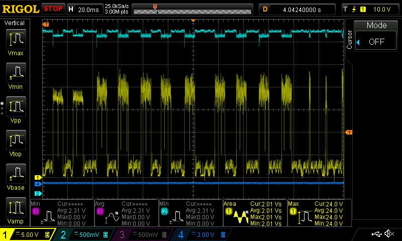
The yellow data in the scope shot above is current to the 9160 @ 3.5V from a benchtop supply. The conversion is V *0.02 = A.
- Peak currents = ~380mA
- Worst case duty cycle is 50% (8ms on / 8ms off).
- Transmission "cycles" can go for ~1s on with 0.5s rest. This repeats for a few seconds.
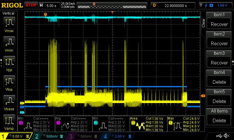
Zoomed out view of the full connection process:
Our alpha design uses two Li-SOCl2 AA batteries in parallel (3.6V typical). I've found that I'll almost definitely need a boost converter to keep the voltage above 3.3V. These batteries are rated to put out 50mA each (100mA total in parallel) continuous current. They are capable of higher peaks, but knowing duty cycle is critical here. The power supply design is proving challenging with these high duty cycle transmissions for long durations.
Questions:
1. What can I expect for worst case transmit duty cycle and overall communication time?
2. Is the duty cycle of transmissions configurable in the 9160 modem? For example, could we limit the duty cycle to 5% in order to reduce stress on our battery?
3. Any examples of power supplies on small batteries with this device would be a nice to have 
Happy holidays! Thanks in advance for the guidance!
