This post is older than 2 years and might not be relevant anymore
More Info: Consider searching for newer posts

Nordic Dongle Power Off mode

I have been struggling to reduce the current on the Nordic Dongle to the  sub 3 uA levels that the specs suggest I should be able to achieve.

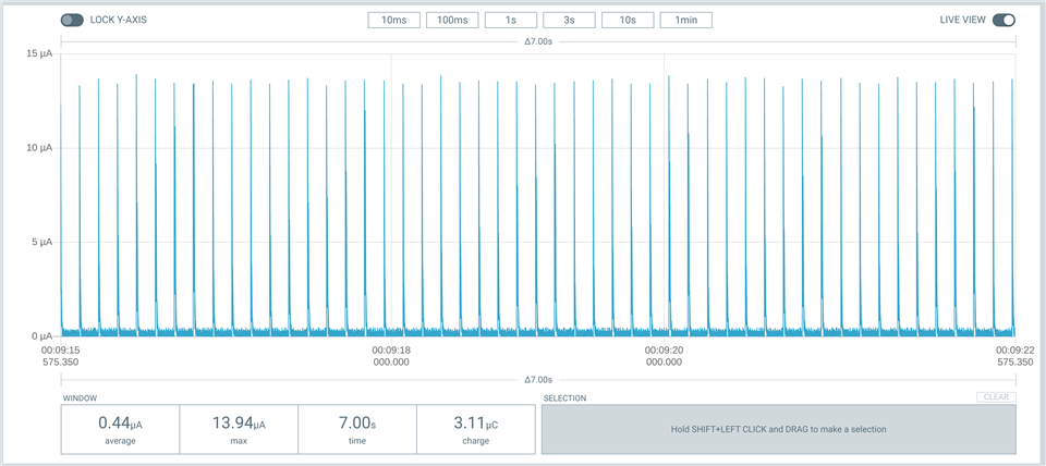
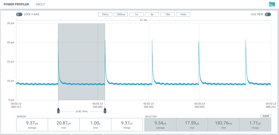
I am stuck at achieving a 9-10 uA current in POWER off mode.

Here is an output from the PPK-II in power off mode.

To achieve this I set up 4 GPIO pins to wakeup the nrf52840 from POWER_OFF mode as follows:

// this will enable wakeup from ultra low power mode (any button press)
nrf_gpio_cfg_sense_input(PLUS__PIN, GPIO_PIN_CNF_PULL_Pullup, GPIO_PIN_CNF_SENSE_Low);
nrf_gpio_cfg_sense_input(MINUS__PIN, GPIO_PIN_CNF_PULL_Pullup, GPIO_PIN_CNF_SENSE_Low);
nrf_gpio_cfg_sense_input(ENTER__PIN, GPIO_PIN_CNF_PULL_Pullup, GPIO_PIN_CNF_SENSE_Low);
nrf_gpio_cfg_sense_input(STANDBY__PIN, GPIO_PIN_CNF_PULL_Pullup, GPIO_PIN_CNF_SENSE_Low);
I also disable the button on the board as follows:
nrf_drv_gpiote_in_event_disable(BUTTON_1);
I also turned off the following
1.ram retention
2. logging in sdk_config.sys.
3.NRF_SPI0->ENABLE = 0;
4.NRF_UART0->ENABLE = 0;
I am using the s340 SD in low power mode:
//set up the pwr configuration
sd_power_mode_set(NRF_POWER_MODE_LOWPWR);
power is from a 3v coin battery connected to the VDD pin, not VBUS to avoid the first conversion stage
Does anybody have any ideas on how I can get below 9 uA in POWER_OFF mode?
I am developing for a CR2032 and pwr is everything!
Parents
  • I am not using the usb port at all.

     I have connected the coin cell to the VDD out pin, and have soldered SB1 to short VBUS to VDD OUT.

    Yes the debugger is not connected, and the board has been reset.

    I created a main() that simply immediately goes into poweroff mode by:

    sd_power_mode_set(NRF_POWER_MODE_LOWPWR);

    so no other functions are called

    Is the S340 softdevice is drawing power when it is in poweroff mode?

    Can you try this on your bench with a dongle and see what you measure?

  • Hi, so I tried measuring here, and I see the same 10 uA in system off.

    I took a closer look at the schematic and you actually have to cut SB2 when powering only on VDD. Otherwise VBUS_nRF will be powered as well, and this is where the leakage occurs. VBUS_nRF should only be powered when the USB is in use, otherwise the USB peripheral will be consuming current. From the spec:

    Symbol Description Min. Typ. Max. Units
    IUSB,DISABLED,VDD

    Current from VDD supply, USB disabled, VBUS supply connected, 256 kB RAM retention, regulator=LDO, CPU sleeping

    3 7 11 µA

    https://infocenter.nordicsemi.com/topic/ps_nrf52840/usbd.html?cp=4_0_0_5_34_13#unique_518559908

  • Thanks for this. The answer certainly makes sense.

    However, when I disconnected SB2 and measured again, I am still measuring about 10uA.

    What did you measure when you cut SB2 on the dongle?

  • UPDATE

    the previous result was on a dongle with SB2 open and SB1 shorted.

    I just tried on a dongle that has BOTH SB2 and SB1 open.

    NOW I see a power OFF current of 0.5uA!

    So there is some effect of the first regulator on VDDH?

  • The VDD and VDDH should be shorted when not using the first regulator stage (following the reference design), which is what you do when you short SB1. I measured 0.4uA in System OFF with this setup.

    I'm pretty sure that the extra 10 uA is due to power on VBUS_nRF, which you get rid of by cutting SB2.

    So my guess is that you did not cut SB2 properly on the first dongle. And on the second dongle that has both SB1 and SB2 open, SB2 was cut properly, which gives you 0.5uA. Can you try to short SB1 on the last dongle where you see 0.5uA? It's enough to just short it with the tip of a screw driver or similar, just to test. Thanks.

    If my assumption is wrong can you please tell me the dongle version number? Maybe they did some changes to the design that I'm not aware of.

    And, you are powering the dongle on the pin called VDD OUT right?

  • Yes, I am powering on VDD out.

    You were right, I did not properly disconnect SB2 on the first dongle.

    When I did, the poweroff current fell to 0.5uA.

    However, this was measure before I shorted SB1.

    I then shorted SB1 on both boards, and there was, as expected, no difference in the poweroff current.

    So , I have the answer,  thank you!

    I see the reference design has it in, but would there be any downside to leaving VDDH floating and not tying it to VDD through the SB1 short? 

    I wanted to simplify the preparation of the dongle, and leaving out the SB1 short would simplify things at little bit by only requiring the sb2 open.

  • rananna said:
    I see the reference design has it in, but would there be any downside to leaving VDDH floating and not tying it to VDD through the SB1 short? 

     All I can say is that the regulator is designed this way (VDD and VDDH shorted) and all production testing we have done to verify our product is with this configuration. So we cannot guarantee that every device will work as expected without VDD and VDDH shorted. So for mass production I would definitely follow the reference design, but for prototyping and testing purposes you will probably be fine by leaving out the SB1 short.

Reply
  • rananna said:
    I see the reference design has it in, but would there be any downside to leaving VDDH floating and not tying it to VDD through the SB1 short? 

     All I can say is that the regulator is designed this way (VDD and VDDH shorted) and all production testing we have done to verify our product is with this configuration. So we cannot guarantee that every device will work as expected without VDD and VDDH shorted. So for mass production I would definitely follow the reference design, but for prototyping and testing purposes you will probably be fine by leaving out the SB1 short.

Children
Related