yes. Thanks for your reply. it's custom board . But i don't have nRF9160-DK,so i can't test with it now.
i have another question, is there a pin used for controling the output of SIM_1V8 .Actually some 4G modules have this pin . And there are two buttons in DK for nRF9160 , what are they used for ?
yes. Thanks for your reply. it's custom board . But i don't have nRF9160-DK,so i can't test with it now.
i have another question, is there a pin used for controling the output of SIM_1V8 .Actually some 4G modules have this pin . And there are two buttons in DK for nRF9160 , what are they used for ?
It is possible to use discrete components to filter.
Discrete ESD protection can consist of the following components: • Bypass capacitors in the range of ≤ 22 pF to SIM_RST, SIM_DET, SIM_CLK, SIM_IO, and SIM_1V8. • A separate supply capacitor ranging from 100 nF to 220 nF connected to SIM_1V8 can be considered.
• Low capacitance type ESD diodes to SIM_RST, SIM_DET, SIM_CLK, SIM_IO, and SIM_1V8. • Multichannel ESD diodes are commonly used and recommended. • Some multichannel diode components incorporate EMI filtering. This type is recommended if the product integrates an LTE antenna or an external antenna is located close to the SIM holder.
Is the SIM holder placed close to any RF components?
If you want you can share the PCB files and i can look at the layout. If you dont want the PCB files to be public then you can make a new private ticket or we can make this ticket private.
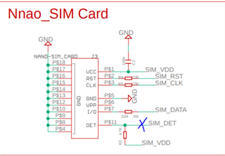
Can you cut\disconnect SIM_DET ?
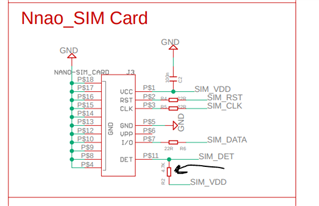
R4, R5 and R22 should not be there or changed to 0 Ohm, the impedance should be as low as possible.
Can you share what nano-SIM card holder you are using ?