This post is older than 2 years and might not be relevant anymore
More Info: Consider searching for newer posts

The status of USB signal pin D+/D- when USBD is disable

Hello Devzone 

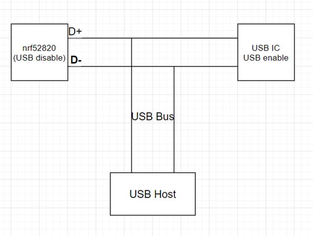
Currently, we have below USBD application scenario

now the user are using the nrf52820 with disable the USB peripheral and they have another USB IC connects to the USB bus.

in the future, they may disable the USB IC and use nrf52820 usb peripheral.

for this user case , we have below questions

1.  if nrf52820 disable the USBD peripheral, does the status of signal PIN D+/D- will show as input disconnect with high impedance?

2.  for above figure, is it ok with this connection setting? Does the singal PIN D+/D- still will inpact USB Bus?(disable USBD)?

BR

  • Hi David

    1. Apparently there is a parasitic coupling between the D+ and D- lines and ground when the USBD peripheral is disabled, since the D+ and D- lines are connected to the DECUSB line by ESD diodes, and DECUSB gets pulled to ground when USBD is disabled. 

    Exactly what impact this has on the impedance is not specified. I will try to find some more specific information about this and get back to you. 

    2. Even if the impedance of the D+ and D- pads on the chip is high you will inevitably get some stray capacitance from such a configuration, and I am not sure you will be able to pass USB certification. This is not a configuration that USB was designed to support, and even with the relatively low clock speed of full speed USB you might have issues trying to certify such a design. 

    In other words it's not something I would recommend if you can find some alternative way to configure your design, such as using a different interface between the nRF chip and the USB IC. 

    Best regards
    Torbjørn

Related