Hello,
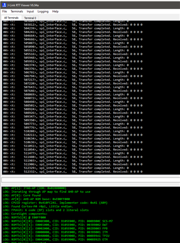
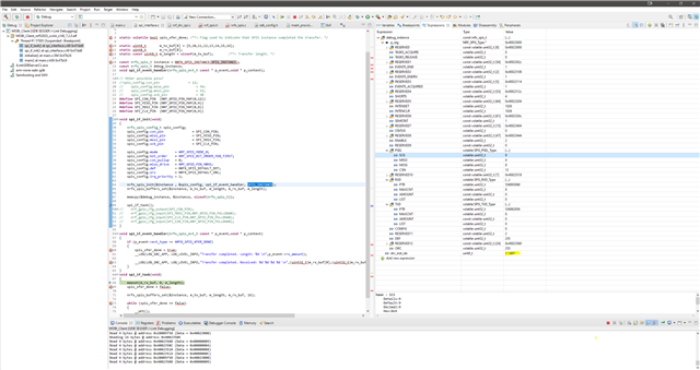
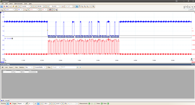
I'm trying to get the SPI drivers working in slave mode. I have tested my master (Atmel L21) on an Arduino and I can see my message clearly. I'm trying to get nRF52833 working in slave mode but p_event->rx_amount always reports back 0.
I have tried all SPI modes (but I believe I'm operating in SPI Mode 2)
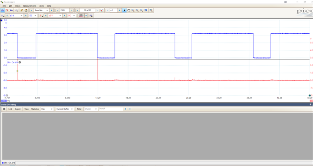
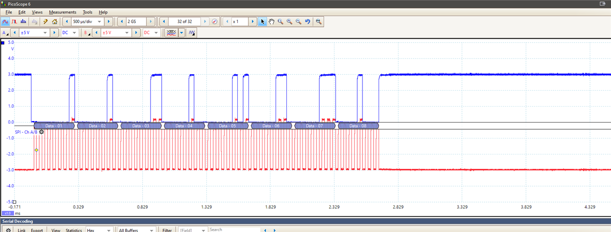
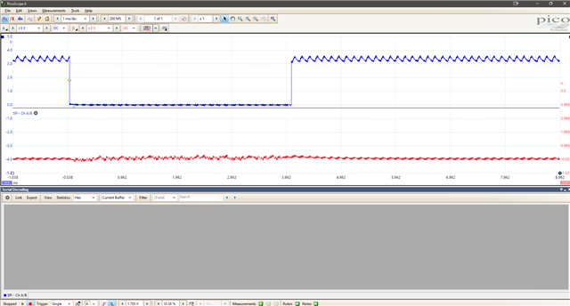
I only get a single blip on the MISO line that goes blips again on the next chip select toggle.
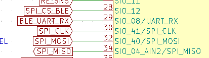
The module in question is a Laird part. It uses mappings like SPI = SIO_41, SIO_41 translates to pin 9 according to their documentation but maybe an expert can point out if this is wrong.
I am in a huge time crunch! This is based off of the spis example code but if any other example works for slave mode (and is better documented about how to get it into slave mode) I'd be open to switching to it.
Thanks!
int main(void)
{
    initialize();
    spi_if_init();
    start();

    for (;;)
    {
        spi_if_task();
        //(void)sd_app_evt_wait();
    }
}
#include <nrfx_spis.h>
#include "spi_interface.h"
#include "log.h"

#define SPIS_INSTANCE 2 /**< SPIS instance index. */


static volatile bool spis_xfer_done; /**< Flag used to indicate that SPIS instance completed the transfer. */

static uint8_t       m_tx_buf[8] = {9,10,11,12,13,14,15,16};
static uint8_t       m_rx_buf[16];
static const uint8_t m_length = sizeof(m_tx_buf);        /**< Transfer length. */

const nrfx_spis_t instance = NRFX_SPIS_INSTANCE(SPIS_INSTANCE);

void spi_if_event_handler(nrfx_spis_evt_t const * p_event,void * p_context);

void spi_if_init(void)
{
    nrfx_spis_config_t spis_config;
    spis_config.csn_pin               = NRF_GPIO_PIN_MAP(0,12);
    spis_config.miso_pin              = NRF_GPIO_PIN_MAP(0,4);
    spis_config.mosi_pin              = NRF_GPIO_PIN_MAP(0,8);
    spis_config.sck_pin               = NRF_GPIO_PIN_MAP(0,9);
//    spis_config.csn_pin               = NRF_GPIO_PIN_MAP(0,12);
//    spis_config.miso_pin              = NRF_GPIO_PIN_MAP(0,34);
//    spis_config.mosi_pin              = NRF_GPIO_PIN_MAP(0,32);
//    spis_config.sck_pin               = NRF_GPIO_PIN_MAP(0,30);
////    spis_config.csn_pin               = 12;
//    spis_config.miso_pin              = 34;
//    spis_config.mosi_pin              = 32;
//    spis_config.sck_pin               = 30;

    spis_config.mode         = NRF_SPIS_MODE_2;
	spis_config.bit_order    = NRF_SPIS_BIT_ORDER_MSB_FIRST;
	spis_config.csn_pullup   = 0;
	spis_config.miso_drive   = NRF_GPIO_PIN_H0H1;
	spis_config.def          = NRFX_SPIS_DEFAULT_DEF;
	spis_config.orc          = NRFX_SPIS_DEFAULT_ORC;
	spis_config.irq_priority = 1;

    nrfx_spis_init(&instance , &spis_config, spi_if_event_handler, SPIS_INSTANCE);
	nrfx_spis_buffers_set(&instance, m_tx_buf, m_length, m_rx_buf, m_length);

    nrf_gpio_cfg_output(4);
    nrf_gpio_cfg_input(32,NRF_GPIO_PIN_PULLDOWN);
    nrf_gpio_cfg_input(30,NRF_GPIO_PIN_PULLDOWN);
    nrf_gpio_cfg_input(12,NRF_GPIO_PIN_PULLDOWN);
}

void spi_if_event_handler(nrfx_spis_evt_t const * p_event,void * p_context)
{
    if (p_event->evt_type == NRFX_SPIS_XFER_DONE)
    {
        spis_xfer_done = true;
        __LOG(LOG_SRC_APP, LOG_LEVEL_INFO,"Transfer completed. Length: %d \n",p_event->rx_amount);

        __LOG(LOG_SRC_APP, LOG_LEVEL_INFO,"Transfer completed. Received: %d %d %d %d \n",(uint32_t)m_rx_buf[0],(uint32_t)m_rx_buf[1],(uint32_t)m_rx_buf[2],(uint32_t)m_rx_buf[3]);
    }
}
void spi_if_task(void)
{
    memset(m_rx_buf, 0, m_length);
    spis_xfer_done = false;

	nrfx_spis_buffers_set(&instance, m_tx_buf, m_length, m_rx_buf, m_length);

    while (spis_xfer_done == false)
    {
        __WFE();
    }
}
Laird module: 453-00041R