This post is older than 2 years and might not be relevant anymore
More Info: Consider searching for newer posts

nRf51822 RF antenna desing

Hello,

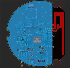
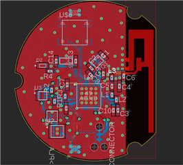
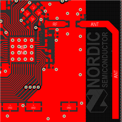
It is my first pcb with a rf-antenna. I have read some articles about the topic an came up with the following inverted f-antenna design (ti inverted f-antenna).

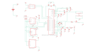
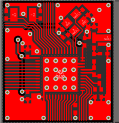
The matching network is copied from the Nordic layout-guide for the nrf51822. My question is, is it mandatory to match the antenna with an extra pi-network or is an 50ohm transmission line enough (calculated here).
ε = 4.5, s = 1.03mm, w = 0.197mm, h = 1mm 

The target range ist about 4-8 meters.

Additionally would anyone commend on my PCB design.

Thank you for your support.

Parents
  • Hi,

    My question is, is it mandatory to match the antenna with an extra pi-network

    It is not mandatory but it is highly recommended.  You can always leve the matching network unpopulated and use a 0 Ohm resistors.  Including a matching network will at lest give you the possibility to tune the device and achieve better performance. 


    Many things will effect the performance of the antenna like casing, placement, available ground plane, noise form other components ect, so getting the 50 Ohm match might not always be spot on. If it is 50 Ohm then a matching circuit is not needed  but its nice to have the option. Especially if you dont plan on makking many iterations. 

    Can you provide the schematic and PCB\Gerber files? I will give you feedback on the PCB layout and schematic. 

    Regards,
    Jonathan

  • Thank you for your advise!

    I added the matching network. But with the additionally parts the transmission line is very short and noncontinuous.

    GerberFiles.zip
    Here the requested files. Thank you!

Reply Children
  • Hi,

    The nrf51 series is sensitive when it comes to harmonics so following the reference as closely as possible is highly recommended. This also applies to the keep-out area:


    Since you have a 2 - layer PCB and I assume that the thickness is 0.8 or grater between the two layers then following keep out from the ref design should be fine. 

    As long as the transmission line is 50 Ohm the length shouldn't matter or that it is noncontiguous.
    Here is the layout for the 51DK for reference:


    Regards,
    Jonathan

Related